高通msm8916 gpio笔记(基于设备树)
1.通用GPIO控制函数:
gpio_set_value(port_num,0/1) 一般只是在这个GPIO口的寄存器上写上某个值,至于这个端口是否设置为输出,它就管不了!而gpio_direction_output (port_num,0/1),在某个GPIO口写上某个值之后,还会把这个端口设置为输出模式。首先要调用gpio_direction_output(),以后要设置高低电平时,直接使用gpio_set_value()就可以了
2.http://wenku.baidu.com/link?url=5ry8VUdQA7-vhasbcfWwfOOTOteFvZCHxWVqAnix3z7kd7TVK4VRPHv22M2C17MAoSdd25mGYCI2qAhs9gwC-TZ1sCVpF24MTBzr8ET3AkGstruct
pinctrl * evm_pinctrl_get(struct device *dev);根据设备获取pin操作句柄,所以的pin操作必须基于此pinctrl句柄。与pinctrl_get接口功能完全一样,只是devm_pinctrl_get会将申请的pinctrl句柄做记账,绑定到设备句柄信息中。
改写后:设备树:msm8916-pinctrl.dtsi
gpio_cameral_flash {
compatible = "qcom,gpio_cameral_flash";
qcom,gpio_cameral_flash = <&msm_gpio 105 0>;
};
驱动:leds-cameral-flash.c
//#include <Linux/types.h>
#include <linux/pm.h>
#include <linux/gpio.h>
#include <linux/slab.h>
#include <linux/init.h>
#include <linux/platform_device.h>
#include <linux/fsl_devices.h>
#include <asm/setup.h>
#include <linux/of.h>
#include <linux/of_gpio.h>
#include <linux/stat.h>
#include <linux/module.h>
#include <linux/err.h>
#include <linux/spinlock.h>
#include <linux/err.h>
#include <linux/regulator/consumer.h>
int gpio_ldo_pin = -1;
int gpio_flag = -1;
static struct class *gpio_cameral_flash_class = NULL;
static struct device *gpio_cameral_flash_dev = NULL;
#define CTL_POWER_ON "1"
#define CTL_POWER_OFF "0"
//cat
static ssize_t gpio_105_show(struct device *dev,
struct device_attribute *attr, char *buf)
{
printk("%s\n", __func__);
sprintf(buf, "gpio_105 is %d\n", gpio_flag);
return strlen(buf);
}
//echo
static ssize_t gpio_105_store(struct device *dev,
struct device_attribute *attr, const char *buf,
size_t count)
{
if(!strncmp(buf, CTL_POWER_ON, strlen(CTL_POWER_ON))) {
printk("%s: to enable gpio_105\n", __func__);
gpio_set_value(gpio_ldo_pin, 1);
gpio_flag = 1;
} else if(!strncmp(buf, CTL_POWER_OFF, strlen(CTL_POWER_OFF))) {
printk("%s: to disable gpio_105\n", __func__);
gpio_set_value(gpio_ldo_pin, 0);
gpio_flag = 0;
}
return count;
}
static struct device_attribute gpio_105_dev_attr = { // /sys/class/gpio_cameral_flash下生成gpio_105设备节点
.attr = {
.name = "gpio_105",
.mode = S_IRWXU|S_IRWXG|S_IRWXO, //节点读写权限设置
},
.show = gpio_105_show, //节点读方法
.store = gpio_105_store, //节点写方法
};
static int gpio_cameral_flash_probe(struct platform_device *pdev)
{
int ret = 0;
printk("qcom enter gpio_cameral_flash_probe \n");
gpio_ldo_pin = of_get_named_gpio(pdev->dev.of_node, "qcom,gpio_cameral_flash", 0);
if (gpio_ldo_pin < 0)
printk("xcz gpio_ldo_pin is not available \n");
ret = gpio_request(gpio_ldo_pin, "gpio_cameral_flash");//取名
if(0 != ret) {
printk("qcom gpio request %d failed.", gpio_ldo_pin);
goto fail1;
}
gpio_direction_output(gpio_ldo_pin, 0);
gpio_set_value(gpio_ldo_pin, 0);
gpio_flag = 0;
gpio_cameral_flash_class = class_create(THIS_MODULE, "gpio_cameral_flash");
if(IS_ERR(gpio_cameral_flash_class))
{
ret = PTR_ERR(gpio_cameral_flash_class);
printk("Failed to create class.\n");
return ret;
}
gpio_cameral_flash_dev = device_create(gpio_cameral_flash_class, NULL, 0, NULL, "gpio_gpio_105");//取名
if (IS_ERR(gpio_cameral_flash_dev))
{
ret = PTR_ERR(gpio_cameral_flash_class);
printk("Failed to create device(gpio_cameral_flash_dev)!\n");
return ret;
}
ret = device_create_file(gpio_cameral_flash_dev, &gpio_105_dev_attr);
if(ret)
{
pr_err("%s: gpio_105 creat sysfs failed\n",__func__);
return ret;
}
printk("xcz enter gpio_cameral_flash_probe, ok \n");
fail1:
return ret;
}
//硬件卸载时调用
static int gpio_cameral_flash_remove(struct platform_device *pdev)
{
device_destroy(gpio_cameral_flash_class, 0);
class_destroy(gpio_cameral_flash_class);
device_remove_file(gpio_cameral_flash_dev, &gpio_105_dev_attr);
return 0;
}
static int gpio_cameral_flash_suspend(struct platform_device *pdev,pm_message_t state)
{
return 0;
}
static int gpio_cameral_flash_resume(struct platform_device *pdev)
{
return 0;
}
static struct of_device_id gpio_cameral_flash_dt_match[] = {
{ .compatible = "qcom,gpio_cameral_flash",},
{ },
};
MODULE_DEVICE_TABLE(of, gpio_cameral_flash_dt_match);
static struct platform_driver gpio_flash_driver = { // /sys/class总线下生成设备节点gpio_cameral_flash
.driver = {
.name = "gpio_cameral_flash",
.owner = THIS_MODULE,
.of_match_table = of_match_ptr(gpio_cameral_flash_dt_match),
},
.probe = gpio_cameral_flash_probe,
.remove = gpio_cameral_flash_remove,
.suspend = gpio_cameral_flash_suspend,
.resume = gpio_cameral_flash_resume,
};
static __init int gpio_flash_init(void)
{
return platform_driver_register(&gpio_flash_driver);
}
static void __exit gpio_flash_exit(void)
{
platform_driver_unregister(&gpio_flash_driver);
}
module_init(gpio_flash_init);
module_exit(gpio_flash_exit);
MODULE_AUTHOR("GPIO_CAMERAL_FLASH, Inc.");
MODULE_DESCRIPTION("QCOM GPIO_CAMERAL_FLASH");
MODULE_LICENSE("GPL");
来源于:
设备树:msm8916-pinctrl.dtsi
gpio_ldo_power {
compatible = "xcz,gpio_ldo_power";
qcom,gpio_ldo_pin = <&msm_gpio 20 0>;
};
驱动:leds-cameral-flash.c
//#include <Linux/types.h>
#include <linux/pm.h>
#include <linux/gpio.h>
#include <linux/slab.h>
#include <linux/init.h>
#include <linux/platform_device.h>
#include <linux/fsl_devices.h>
#include <asm/setup.h>
#include <linux/of.h>
#include <linux/of_gpio.h>
#include <linux/stat.h>
#include <linux/module.h>
#include <linux/err.h>
#include <linux/spinlock.h>
#include <linux/err.h>
#include <linux/regulator/consumer.h>
int gpio_ldo_pin = -1;
int gpio_flag = -1;
static struct class *gpio_ldo_power_class = NULL;
static struct device *gpio_ldo_power_dev = NULL;
#define CTL_POWER_ON "1"
#define CTL_POWER_OFF "0"
//cat
static ssize_t gpio_22_show(struct device *dev,
struct device_attribute *attr, char *buf)
{
printk("%s\n", __func__);
sprintf(buf, "gpio_22 is %d\n", gpio_flag);
return strlen(buf);
}
//echo
static ssize_t gpio_22_store(struct device *dev,
struct device_attribute *attr, const char *buf,
size_t count)
{
if(!strncmp(buf, CTL_POWER_ON, strlen(CTL_POWER_ON))) {
printk("%s: to enable gpio_22\n", __func__);
gpio_set_value(gpio_ldo_pin, 1);
gpio_flag = 1;
} else if(!strncmp(buf, CTL_POWER_OFF, strlen(CTL_POWER_OFF))) {
printk("%s: to disable gpio_22\n", __func__);
gpio_set_value(gpio_ldo_pin, 0);
gpio_flag = 0;
}
return count;
}
static struct device_attribute gpio_22_dev_attr = {
.attr = {
.name = "gpio_22",
.mode = S_IRWXU|S_IRWXG|S_IRWXO,
},
.show = gpio_22_show,
.store = gpio_22_store,
};
static int gpio_ldo_power_probe(struct platform_device *pdev)
{
int ret = 0;
printk("xcz enter gpio_ldo_power_probe \n");
gpio_ldo_pin = of_get_named_gpio(pdev->dev.of_node, "qcom,gpio_ldo_pin", 0);
if (gpio_ldo_pin < 0)
printk("xcz gpio_ldo_pin is not available \n");
ret = gpio_request(gpio_ldo_pin, "gpio_ldo_pin");
if(0 != ret) {
printk("xcz gpio request %d failed.", gpio_ldo_pin);
goto fail1;
}
gpio_direction_output(gpio_ldo_pin, 0);
gpio_set_value(gpio_ldo_pin, 0);
gpio_flag = 0;
gpio_ldo_power_class = class_create(THIS_MODULE, "gpio_ldo_power");
if(IS_ERR(gpio_ldo_power_class))
{
ret = PTR_ERR(gpio_ldo_power_class);
printk("Failed to create class.\n");
return ret;
}
gpio_ldo_power_dev = device_create(gpio_ldo_power_class, NULL, 0, NULL, "gpio_gpio_22");
if (IS_ERR(gpio_ldo_power_dev))
{
ret = PTR_ERR(gpio_ldo_power_class);
printk("Failed to create device(gpio_ldo_power_dev)!\n");
return ret;
}
ret = device_create_file(gpio_ldo_power_dev, &gpio_22_dev_attr);
if(ret)
{
pr_err("%s: gpio_22 creat sysfs failed\n",__func__);
return ret;
}
printk("xcz enter gpio_ldo_power_probe, ok \n");
fail1:
return ret;
}
//硬件卸载时调用
static int gpio_ldo_power_remove(struct platform_device *pdev)
{
device_destroy(gpio_ldo_power_class, 0);
class_destroy(gpio_ldo_power_class);
device_remove_file(gpio_ldo_power_dev, &gpio_22_dev_attr);
return 0;
}
static int gpio_ldo_power_suspend(struct platform_device *pdev,pm_message_t state)
{
return 0;
}
static int gpio_ldo_power_resume(struct platform_device *pdev)
{
return 0;
}
static struct of_device_id gpio_ldo_power_dt_match[] = {
{ .compatible = "xcz,gpio_ldo_power",},
{ },
};
MODULE_DEVICE_TABLE(of, gpio_ldo_power_dt_match);
static struct platform_driver gpio_power_driver = {
.driver = {
.name = "gpio_ldo_power",
.owner = THIS_MODULE,
.of_match_table = of_match_ptr(gpio_ldo_power_dt_match),
},
.probe = gpio_ldo_power_probe,
.remove = gpio_ldo_power_remove,
.suspend = gpio_ldo_power_suspend,
.resume = gpio_ldo_power_resume,
};
static __init int gpio_power_init(void)
{
return platform_driver_register(&gpio_power_driver);
}
static void __exit gpio_power_exit(void)
{
platform_driver_unregister(&gpio_power_driver);
}
module_init(gpio_power_init);
module_exit(gpio_power_exit);
MODULE_AUTHOR("GPIO_LDO_POWER, Inc.");
MODULE_DESCRIPTION("XCZ GPIO_LDO_POWER");
MODULE_LICENSE("GPL");
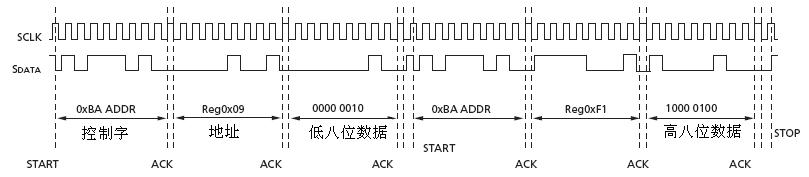
关于高通8053平台i2c和spi配置的学习总结
发表于2016/9/29 17:16:02 858人阅读
分类: 技术
高通msm8916 gpio笔记(基于设备树)相关推荐
- 基于设备树的中断实现 (24x0平台)
文章目录 一.平台信息 1. 平台信息 二.中断的驱动实现方式 2. 不使用设备树的中断实现 2.1 mach-mini2440.c文件中注册中断 2.2 注册中断 3. 使用设备树的中断实现 设备树 ...
- 【MIUI9_7.12.05】小米6 sagit 高通骁龙835 基于安卓N(Android 7.1)时间刺客修改精简优化版本
小米6 sagit 高通骁龙835 基于安卓N(Android 7.1) MIUI9 时间刺客修改精简优化版本 搞机条款:(温馨提醒,不看者默认代表同意!) (1)本人任何刷机包均自带Supersu_ ...
- 嵌入式编程笔记之六--设备树初体验
设备树的起源 设备树(Device Tree)是一种描述硬件资源的数据结构,它由 uboot 传递给 Linux 内核,被内核解析,内核根据设备树中的硬件描述信息加载利用相应驱动资源.在引入设备树之前 ...
- Zynq SOC学习笔记之设备树
一. 概述 DTS即DeviceTree Source 设备树源码,是一种描述硬件的数据结构 以树状节点的方式描述一个设备的各种硬件信息细节:CPU.GPIO.时钟.中断.内存等,形成类似文本文件dt ...
- 基于设备树的TQ2440的中断(2)
下面以按键中断为例看看基于设备数的中断的用法: 设备树: tq2440_key {compatible = "tq2440,key";interrupt-parent = < ...
- 高通平台GPIO模拟PWM控制背光
很多时候由于节省硬件资源,降低成本,会把PWM控制芯片去掉或者是改做它用,导致当我们想用PWM方式控制背光时只能使用带有clk功能的GPIO口.本篇文档就来讲解下如何使用GPIO模拟PWM功能进行背光 ...
- TP X 双击唤醒 X 高通msm8916 X 方案1
最近要实现双击唤醒屏幕 第一个方案:勉强实现,但是功耗大,还没进行消抖处理 实现步骤如下: 1.找到tp实现的代码kernel/drivers/input/touchscreen/gsl/gslX68 ...
- 使用高通QXDM工具实现Android设备网络制式更改(如仅注册LTE网络)(独家!)
修改网络制式需要用到高通的QXDM工具,该工具包下载链接如下: 链接:https://pan.baidu.com/s/1rRNicFvlRSstUhka2JSiOg 密码:pssp 具体操作步骤如下: ...
- 高通QCC5181蓝牙芯片耳机修改设备名称
这里一共有三种方法 一.读写pskey方式实现 通过高通提供的接口,读写pskey的方式实现,主要修改的是app5的值. 二.修改烧录测试脚本实现 主要是修改烧录测试脚本ptsetup.txt,去掉烧 ...
- 高通平台GPIO漏电问题分析方法
在Android智能手机项目开发过程中,我们经常会遇到GPIO漏电导致系统底电流偏高.故总结一下: 1.首先建议HW将怀疑漏电的GPIO与外围电路彻底断开 2.如果依然漏电,使用命令检查GPIO状态: ...
最新文章
- 一文看懂深度学习模型压缩和加速
- 兼顾效率与安全:如何制止新模版注入漏洞?
- Go gin使用html模板
- i7怎么老是显示无服务器,i7处理器真有这么差?网友:懂电脑的人都不买!
- java操作redis的操作_Java操作redis简单示例
- html为何转换为json,将HTML元素的“样式”属性转换为JSON
- 无需用户输入,Adobe提出自动高质量图像合成新方法
- A. 解决运行php文件出现乱码的问题
- 智能语音识别系统-解决方案.pdf
- 图像局部特征(二十)--Textons
- 衡量失败检测算法的指标
- 由数据范围反推算法时间复杂度和需要用到的算法类型
- Centos--swoole平滑重启服务
- 【转载】透视“专利恶霸”系列之一 双重标准 吃相难看
- v.douyin.com/xxx抖音网址官方生成制作抖音缩短口令网址php接口方法
- Learn OpenGL 笔记5.11 Anti Aliasing(抗锯齿)
- 零基础学习3D建模,第一步:3D建模软件有哪些?给你科普一下
- 升级mac最新系统macOS Catalina 10.15
- Django框架--一--安装,工程创建,应用创建,配置,基础操作介绍
- Eth-Trunk捆绑技术