javascript 建模_如何用JavaScript编写3D建模应用程序
javascript 建模
介绍 (Introduction)
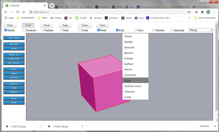
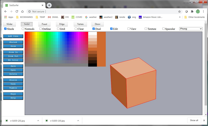
Modeling in Subsurfer is based on cubes, and every model starts as a cube. The buttons at the top select the current tool. Using the Solid tool, you can right-click on a solid and change some of its attributes, such as color. Panning, zooming and rotation of the model are done using the Slider tool. The context menus and color picker are implemented within the Canvas control. This 3D projection and all model editing are done in the 2D context.
Subsurfer中的建模基于多维数据集,每个模型都以多维数据集开始。 顶部的按钮选择当前工具。 使用实体工具,可以右键单击实体并更改其某些属性,例如颜色。 使用“滑块”工具完成模型的平移,缩放和旋转。 上下文菜单和颜色选择器在Canvas控件中实现。 此3D投影和所有模型编辑均在2D上下文中完成。
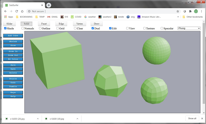
Models are developed by applying successive subdivision surfaces to solids, combined with extrusion and splitting of facets. The interface is a combination of keystroke commands plus right-click menus using the Solid, Facet, Edge and Vertex tools. Here, we see successive applications of surface subdivision on a cube.
通过将连续的细分曲面应用于实体,并结合了小平面的挤压和分割来开发模型。 该界面结合了击键命令以及使用Solid,Facet,Edge和Vertex工具的右键单击菜单。 在这里,我们看到了多维数据集上曲面细分的连续应用。
The check boxes control viewing options. Here, we see the same model with Clear and Outline options checked.
复选框控制查看选项。 在这里,我们看到选中了“ 清除”和“ 轮廓”选项的相同模型。
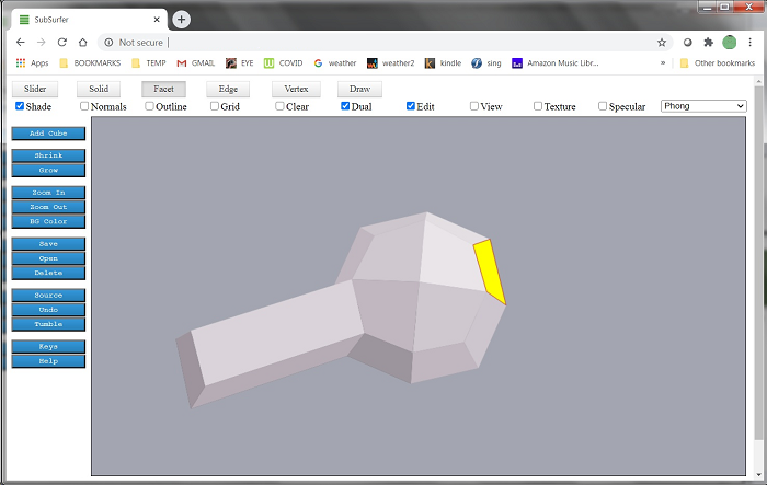
Here, we see a facet that has been extruded. Extrusion is a right-click menu item and a keystroke command. Facets are selected using the Facet tool. You can click a facet, click and roll to select several facets, or drag a box to net-select facets.
在这里,我们看到一个已拉伸的构面。 挤出是右键单击菜单项和击键命令。 使用“构面”工具选择构面。 您可以单击构面,单击并滚动以选择多个构面,或拖动框以净选择构面。
One important thing when extruding facets is to avoid having common internal walls. This can happen when extruding multiple adjacent facets whose normals are pointing in the same direction. Shared internal walls will confuse the Catmull-Clark algorithm and the results don't look right. To avoid this, when extruding adjacent facets, unless their normals are facing in different directions, it's better to use the Extrude Group command.
挤压小平面时,重要的一件事是避免具有共同的内壁。 拉伸法线指向相同方向的多个相邻面时,可能会发生这种情况。 共享的内墙会混淆Catmull-Clark算法,并且结果看起来不正确。 为避免这种情况,在拉伸相邻的构面时,除非其法线朝向不同的方向,否则最好使用“拉伸组”命令。
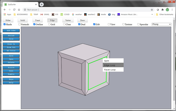
Edge loops affect how surface subdivision will shape a model. Edge loops can be added by using the Bevel command (Facet tool), or using the Split command (Edge tool). Edge loops can be selected with a right-click menu option of the Edge tool.
边缘环会影响曲面细分如何塑造模型。 可以使用“斜角”命令(“ Facet”工具)或“拆分”命令(“边缘”工具)添加边缘环。 可以使用Edge工具的右键菜单选项选择Edge loop。
Every facet in Subsurfer is a quadrilateral. Quadrilaterals are handled well by the Catmull-Clark algorithm, and they make it easier to implement algorithms which can traverse the model to find edge loops and facet loops.
Subsurfer中的每个方面都是四边形。 Catmull-Clark算法可以很好地处理四边形,它们使实现遍历模型的算法更容易实现,从而可以找到边缘环和构面环。
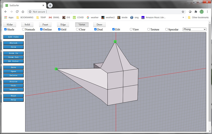
The vertex tool can be used to drag vertices, just as the Facet tool can drag facets and the Edge tool can drag edges. When dragging model elements, it is important to have the grid displayed (Grid check box option) so you will be aware of which 2 dimensions you are dragging in. Otherwise, the results may be unexpected and unwelcome.
可以使用“顶点”工具拖动顶点,就像“构面”工具可以拖动构面,而“边缘”工具可以拖动边缘一样。 拖动模型元素时,显示网格非常重要(“网格”复选框选项),这样您就知道要拖动哪个2维。否则,结果可能会出乎意料且不受欢迎。
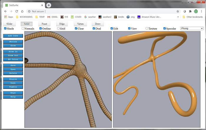
Subsurfer has an Edit window (2D canvas context) and a View window (3D canvas context). They are controlled by the Edit and View check boxes. Here, we see a model in the Edit window alongside its WebGL equivalent in the View window.
子冲浪者具有“编辑”窗口(2D画布上下文)和“查看”窗口(3D画布上下文)。 它们由“编辑”和“查看”复选框控制。 在这里,我们在“编辑”窗口中看到一个模型,在“视图”窗口中看到它的等效WebGL。
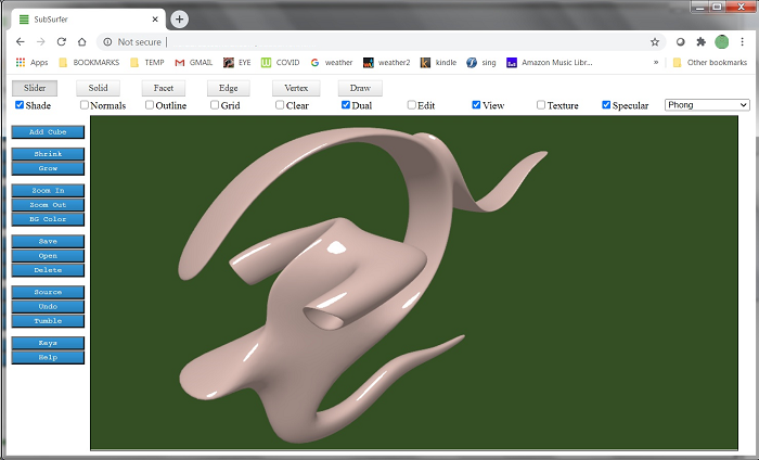
Subdivision surface modeling produces shapes with smoothly rounded curves. With careful planning and patient editing, complex models can be produced by extrusion, splitting, scaling and tilting of facets, translation of edges and vertices, and successive applications of the smoothing algorithm.
细分曲面建模可生成具有平滑圆形曲线的形状。 通过仔细计划和患者编辑,可以通过挤压,分割,缩放和倾斜构面,平移边缘和顶点以及连续应用平滑算法来生成复杂的模型。
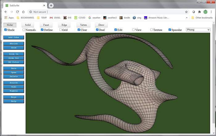
Here is the mesh view of the spacepig model in the Edit window. Like all Subsurfer models, it started as a cube.
这是“编辑”窗口中spacepig模型的网格视图。 像所有Subsurfer模型一样,它以多维数据集开始。
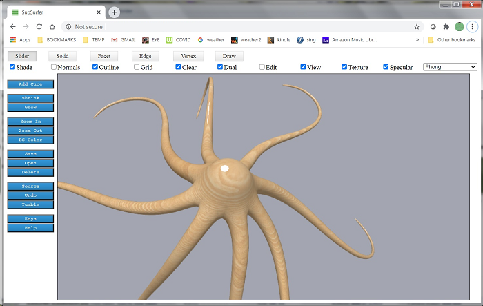
Subsurfer supports a handful of built-in textures, such as wood grain (shown below). An image file called textures.png contains all the textures.
Subsurfer支持一些内置纹理,例如木纹(如下所示)。 名为textures.png的图像文件包含所有纹理。
If you want to run the program from your file system, browser security settings will not allow the web page to load the texture image. Both the HTML page and the PNG image have to be hosted on the same server. You can run the program from localhost if you have the proper software to set that up. Or you can run Chrome.exe with a special command line option to allow loading of the textures from the file system. The command you need to execute is "chrome.exe --allow-file-access-from-files". You will have to close all instances of Chrome before doing this.
如果要从文件系统运行该程序,则浏览器安全设置将不允许该网页加载纹理图像。 HTML页面和PNG图像都必须托管在同一服务器上。 如果您具有适当的软件来进行设置,则可以从localhost运行该程序。 或者,您可以运行带有特殊命令行选项的Chrome.exe ,以允许从文件系统加载纹理。 您需要执行的命令是“ chrome.exe --allow-file-access-from-files ”。 在执行此操作之前,您必须关闭所有Chrome实例。
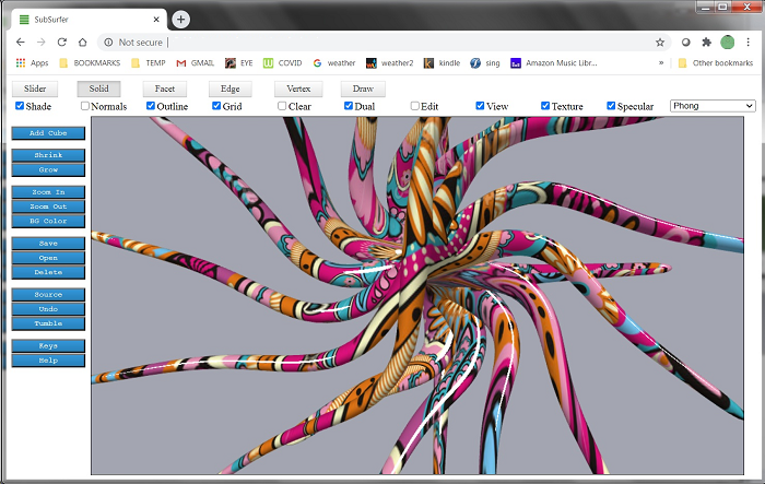
A variety of textures are included, including the mod paisley seen below. There is an Extrude Series command that automates successive extrusion of facets, which lends itself to the creation of hallucinatory, Lovecraftian nightmares.
包括各种纹理,包括下面看到的mod佩斯利。 有一个“挤压系列”命令可以自动连续进行刻面的挤压,这有助于创建幻觉的洛夫克拉夫特式噩梦。
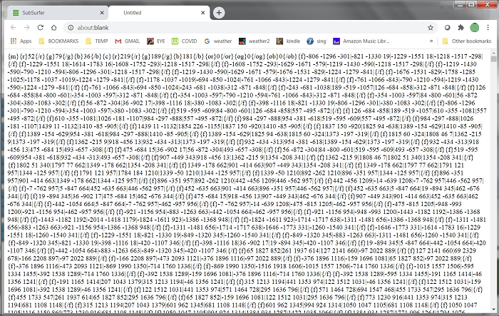
The Source command (left side buttons) opens a new tab that displays a text representation of the current model mesh.
Source命令(左侧按钮)打开一个新选项卡,该选项卡显示当前模型网格的文本表示。
The Save, Open and Delete buttons were implemented and tested using AJAX calls to store the models on a server and retrieve them by name. But since I don't want any hits on my server for the purposes of this article, I have changed the paths and names so the buttons don't do anything. You could still use the AJAX code provided, but you would have to implement your own SOAP web services and change the client side code to match.
使用AJAX调用实现并测试了Save , Open和Delete按钮,以将模型存储在服务器上并按名称检索它们。 但是由于本文不希望对服务器造成任何影响,因此我更改了路径和名称,因此按钮不会执行任何操作。 您仍然可以使用提供的AJAX代码,但是您必须实现自己的SOAP Web服务并更改客户端代码以匹配。
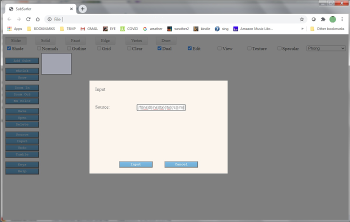
However, you can still save your models in a local file by copying the text from the Source command as shown above. If you want to enter a model you've saved locally into Subsurfer, use the Input button. It's one of the commands on the left hand side, but it's not shown on these pictures. The Input command brings up a form and you just paste the mesh text into the field as shown below. This seems to work quite well even for large models. You may run into issues with browser security settings, but it worked fine for me.
但是,您仍然可以通过复制Source命令中的文本来将模型保存在本地文件中,如上所示。 如果要输入已本地保存到Subsurfer中的模型,请使用“ 输入”按钮。 这是左侧的命令之一,但未在这些图片上显示。 Input命令将显示一个表单,您只需将网格文本粘贴到字段中,如下所示。 即使对于大型模型,这似乎也很好用。 您可能会遇到浏览器安全设置方面的问题,但对我来说效果很好。
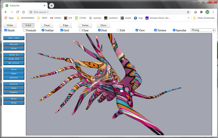
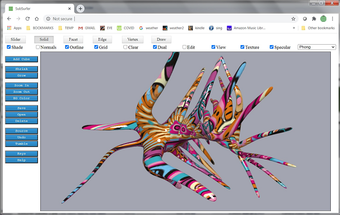
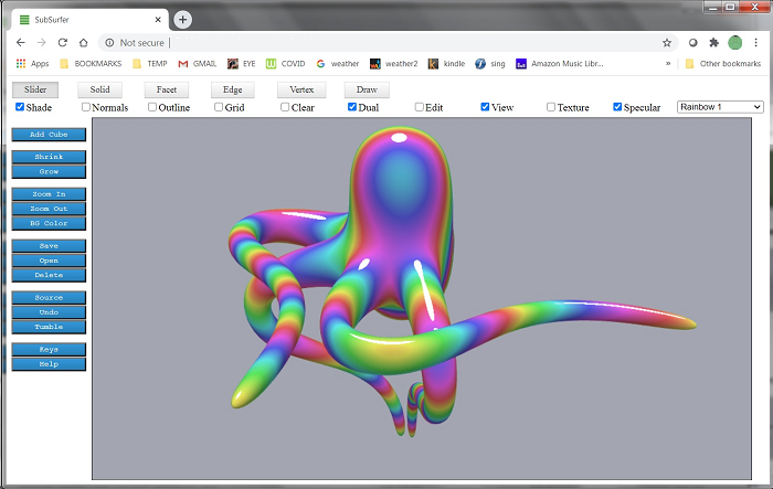
A variety of WebGL shaders are included which can be chosen from the dropdown menu at the top right. Shaders in WebGL are implemented using GLSL. Flat shading and Phong (smooth) shading with optional specularity are the most useful. Flat shading should be used for sharp-edged objects. Cubes look funny with Phong shading. I have also implemented a few non-realistic custom shaders, including the festive rainbow shader pictured below (this is not a texture, it's a custom shader). This shader is sensitive to the object's location in space, so the colors will change in a very trippy way as the object rotates.
包括各种WebGL着色器,可以从右上角的下拉菜单中进行选择。 WebGL中的着色器是使用GLSL实现的。 平面阴影和带有可选镜面反射性的Phong(平滑)阴影最有用。 锋利物体应使用平面阴影。 Phong阴影使多维数据集看起来很有趣。 我还实现了一些非现实的自定义着色器,包括下图所示的节日彩虹着色器(这不是纹理,它是自定义着色器)。 此着色器对对象在空间中的位置很敏感,因此随着对象旋转,颜色将以非常混乱的方式变化。
There is a help file and a list of keystrokes built into the program (last two buttons on left side), but the quickest way to get started playing with Subsurfer is to experiment by extruding facets and smoothing solids using keystroke commands, just to see what kinds of weird and interesting models you can make. The keystroke command to extrude a facet is 'e' and the keystroke command to smooth a solid is 's'. You will want to have the Facet tool chosen so you can select facets. You can rotate the model using the Facet tool (and most of the other tools) by doing right-click + dragging in the window. Plus and minus keys will zoom in or out. Click on a facet to select it. You can also net select facets and click+drag to select areas. It's possible to extrude multiple facets at the same time. But if doing multiple extrudes, make sure the facets are not facing in the exact same direction or you will end up with shared internal walls that throw off the subdivision algorithm. If extruding neighboring facets that face the same direction, better to use Extrude Group (keystroke 'g') instead.
程序中内置了一个帮助文件和一个击键列表(左侧的最后两个按钮),但是开始使用Subsurfer最快的方法是通过使用击键命令拉伸刻面并平滑实体来进行实验,只是为了了解一下您可以制作各种奇怪而有趣的模型。 挤压小平面的击键命令为“ e ”,平滑实体的击键命令为“ s ”。 您将需要选择“构面”工具,以便可以选择构面。 您可以通过使用Facet工具(以及其他大多数工具)来旋转模型,方法是在窗口中右键单击并拖动。 加号和减号键将放大或缩小。 单击构面以将其选中。 您也可以净选择面,然后单击+拖动以选择区域。 可以同时挤压多个面。 但是,如果要进行多次拉伸,请确保切面未完全朝着相同的方向,否则最终将遇到共享的内墙,从而无法使用细分算法。 如果拉伸面对相同方向的相邻小平面,则最好使用“拉伸组”(按键“ g ”)。
使用代码 (Using the Code)
You can just run the HTML file from your local file system. As mentioned above, if running locally, you will run into security issues and textures will not display in WebGL.
您可以只从本地文件系统运行HTML文件。 如上所述,如果在本地运行,则会遇到安全问题,并且纹理将不会显示在WebGL中。
To get around this problem, close all instances of Chrome and start Chrome with this command: "chrome.exe --allow-file-access-from-files".
要解决此问题,请关闭所有Chrome实例,然后使用以下命令启动Chrome:“ chrome.exe --allow-file-access-from-files ”。
Also, the Save, Open and Delete buttons are effectively disabled. To save a model, copy the mesh specification using the Source command (left-hand buttons). To enter the saved model into Subsurfer, use the Input command and paste the mesh text into the form provided.
同样,“ 保存” ,“ 打开”和“ 删除”按钮也被有效禁用。 要保存模型,请使用Source命令(左侧按钮)复制网格规格。 要将输入的模型输入到Subsurfer中,请使用Input命令并将网格文本粘贴到提供的表单中。
One important thing when extruding facets is to avoid having common internal walls. This can happen when extruding multiple adjacent facets whose normals are pointing in the same direction. Internal walls will mess up the results of the Catmull-Clark algorithm. To avoid this, when extruding adjacent facets, unless their normals are facing in different directions, it's better to use the Extrude Group command.
挤压小平面时,重要的一件事是避免具有共同的内壁。 拉伸法线指向相同方向的多个相邻面时,可能会发生这种情况。 内墙会弄乱Catmull-Clark算法的结果。 为避免这种情况,在拉伸相邻的构面时,除非其法线朝向不同的方向,否则最好使用“拉伸组”命令。
构建编辑视图 (Building the Edit View)
There are about 14000 lines of code in the application. The WebGL part makes use of the Sylvester matrix math library of James Coglan, which is used per the license agreement. In this article I will touch on a few of the basic elements that make the program work. I may cover some topics more in depth in future articles.
该应用程序中大约有14000行代码。 WebGL部分使用了James Coglan的Sylvester矩阵数学库,该库根据许可协议使用。 在本文中,我将介绍使程序正常工作的一些基本元素。 我可能会在以后的文章中更深入地介绍一些主题。
This section is about how the 3D projection for the edit view is produced in a 2D drawing context.
本节介绍如何在2D绘图上下文中生成用于编辑视图的3D投影。
The program makes use of the HTML5 Canvas control, which has two contexts. Here is the function which initializes the program UI. It adds two Canvas controls and obtains the 2D context for one and the webgl (3D) context for the other one. If webgl is not available, it falls back to experimental-webgl. The WebGL features seem well supported on all major browsers. The rest of the code sets up listeners for user input and attends to other housekeeping such as adding the available shader options to a listbox.
该程序利用了具有两个上下文HTML5 Canvas控件。 这是初始化程序UI的函数。 它添加了两个Canvas控件,并获得了一个的2D上下文和另一个的webgl(3D)上下文。 如果webgl不可用,它会退回到experimental-webgl。 WebGL功能似乎在所有主要浏览器上均受良好支持。 其余的代码将设置侦听器以供用户输入,并负责其他管理工作,例如将可用的着色器选项添加到listbox 。
function startModel()
{alertUser("");filename = "";setInterval(timerEvent, 10);makeCube();canvas = document.createElement('canvas');canvas2 = document.createElement('canvas');document.body.appendChild(canvas);document.body.appendChild(canvas2);canvas.style.position = 'fixed';canvas2.style.position = 'fixed';ctx = canvas.getContext('2d');gl = canvas2.getContext("webgl") || canvas2.getContext("experimental-webgl");pos = new Point(0, 0); // last known positionlastClickPos = new Point(0, 0); // last click positionwindow.addEventListener('resize', resize);window.addEventListener('keydown', keyDown);window.addEventListener('keyup', keyRelease);canvas.addEventListener('mousemove', mouseMove);canvas.addEventListener('mousedown', mouseDown);canvas.addEventListener('mouseup', mouseUp);canvas.addEventListener('mouseenter', setPosition);canvas.addEventListener('click', click);canvas2.addEventListener('mousemove', mouseMoveGL);canvas2.addEventListener('mousedown', mouseDownGL);canvas2.addEventListener('mouseup', mouseUpGL);    canvas.style.backgroundColor = colorString(canvasBackgroundColor, false);canvas.style.position = "absolute";canvas.style.border = '1px solid black';    canvas2.style.position = "absolute";canvas2.style.border = '1px solid black';    resize();document.getElementById("checkboxoutlines").checked = false;document.getElementById("checkboxsolid").checked = true;document.getElementById("checkboxgrid").checked = false;document.getElementById("toolslider").checked = true;document.getElementById("checkboxtwosided").checked = true;document.getElementById("checkboxwebgl").checked = false;document.getElementById("checkbox2DWindow").checked = true;document.getElementById("checkboxtransparent").checked = false;if (gl != null){    gl.clearColor(canvasBackgroundColor.R / 255.0, canvasBackgroundColor.G / 255.0, canvasBackgroundColor.B / 255.0, 1.0);gl.enable(gl.DEPTH_TEST);gl.depthFunc(gl.LEQUAL);gl.clear(gl.COLOR_BUFFER_BIT | gl.DEPTH_BUFFER_BIT);}addShaderToList("Phong");addShaderToList("Rainbow 1");addShaderToList("Rainbow 2");addShaderToList("Stripes");addShaderToList("Chrome");addShaderToList("Smear");addShaderToList("Flat");addShaderToList("T-Map");addShaderToList("Comic");addShaderToList("Comic 2");addShaderToList("Topo");addShaderToList("Paint By Numbers");var rect = canvas.getBoundingClientRect();origin = new Point(-(rect.width / 2), -(rect.height / 2));setEditViewOptions();hideInputForm();
}
For various reasons, all the editing in the program is done in a 2D context because it seemed easier for me to solve problems related to hit detection and user interaction in the 2D context. Drawing in the 2D context is also a lot simpler than drawing in WebGL.
由于各种原因,程序中的所有编辑都是在2D上下文中完成的,因为对于我来说,解决与2D上下文中的点击检测和用户交互有关的问题似乎比较容易。 在2D上下文中进行绘制也比在WebGL中进行绘制简单得多。
There are only a few things that need to happen in order to create a 3D projection in 2D. Here is the projection code that maps a 3D point into two dimensions. To accomplish this, it is only necessary to imagine an X/Y plane situated along the Z axis between the model and the eye of the viewer. Then calculate where a ray drawn from the eye to each 3D model vertex would intersect that plane.
在2D模式下创建3D投影只需要发生几件事。 这是将3D点映射到二维的投影代码。 为此,仅需要想象在模型和观看者的眼睛之间沿Z轴放置的X / Y平面。 然后计算从眼睛到每个3D模型顶点的光线与该平面相交的位置。
function To2D(p3d) // gives a 3D->2D perspective projection
{var point3d = new Point3D(p3d.x, p3d.y, p3d.z);RotateXYZ(point3d, myCenter, radiansX, radiansY, radiansZ);var xRise = point3d.x - myCenter.x;var yRise = point3d.y - myCenter.y;var zRunEye = zEyePlane - point3d.z;var zRunView = zViewingPlane - point3d.z;var factor = (zRunEye - zRunView) / zRunEye;var x = (myCenter.x + (factor * xRise));var y = (myCenter.y + (factor * yRise));x *= ctx.canvas.width;x /= docSize;y *= ctx.canvas.width;y /= docSize;var p = new Point(Math.floor(x), -Math.floor(y)); // have to flip sign of Y coordinate, this makes it match the GL sidep.x -= origin.x;p.y -= origin.y;return p;
}
Note that the first thing the above function does is to rotate the point from its actual position to the current viewing position. This is to provide a way for the user to rotate the work and view it from all sides. This too is a trivial matter as seen below. Whenever the user enters mouse input to rotate the view, the variables radiansX, radiansY and radiansZ are updated and the projection is redrawn.
请注意,上述功能要做的第一件事是将点从其实际位置旋转到当前查看位置。 这为用户提供了一种旋转作品并从各个角度查看作品的方式。 如下所示,这也是一件无关紧要的事情。 每当用户输入鼠标输入以旋转视图时,变量radiansX , radiansY和radiansZ更新,并且投影会重新绘制。
function RotateXYZ(p, rotation_point, radiansX, radiansY, radiansZ)
{if (radiansZ != 0.0) // rotate about Z axis{radiansZ = normalize_radians(radiansZ);if (radiansZ != 0){var ydiff = (p.y) - (rotation_point.y);var xdiff = (p.x) - (rotation_point.x);var xd = (xdiff * Math.cos(radiansZ)) - (ydiff * Math.sin(radiansZ));xd = Math.round(xd, 0);var yd = (xdiff * Math.sin(radiansZ)) + (ydiff * Math.cos(radiansZ));yd = Math.round(yd, 0);p.x = rotation_point.x + (xd);p.y = rotation_point.y + (yd);}}if (radiansY != 0.0) // rotate about the Y axis{radiansY = normalize_radians(radiansY);if (radiansY != 0){var zdiff = (p.z) - (rotation_point.z);var xdiff = (p.x) - (rotation_point.x);var xd = (xdiff * Math.cos(radiansY)) - (zdiff * Math.sin(radiansY));xd = Math.round(xd, 0);var zd = (xdiff * Math.sin(radiansY)) + (zdiff * Math.cos(radiansY));zd = Math.round(zd, 0);p.x = rotation_point.x + (xd);p.z = rotation_point.z + (zd);}}if (radiansX != 0.0) // rotate about the X axis{radiansX = normalize_radians(radiansX);if (radiansX != 0){var ydiff = (p.y) - (rotation_point.y);var zdiff = (p.z) - (rotation_point.z);var zd = (zdiff * Math.cos(radiansX)) - (ydiff * Math.sin(radiansX));zd = Math.round(zd, 0);var yd = (zdiff * Math.sin(radiansX)) + (ydiff * Math.cos(radiansX));yd = Math.round(yd, 0);p.z = rotation_point.z + (zd);p.y = rotation_point.y + (yd);}}
}
A model consists of facets. Facets consist of edges, and edges consist of points. Here are the basic data structures that hold a model. Please note that for the purposes of this program, a cube is still a cube no matter how many facets it has. Every model starts as a cube with 6 facets, but more facets will be added to the cube as extrusions, splits, and smoothing algorithms are applied.
模型由构面组成。 构面由边组成,而边由点组成。 这是保存模型的基本数据结构。 请注意,就该程序而言,无论它有多少个面,多维数据集仍然是一个多维数据集。 每个模型都以具有6个切面的多维数据集开始,但是当应用拉伸,分割和平滑算法时,会将更多切面添加到多维数据集中。
function cube(left, right, top, bottom, front, back)
{if (left == undefined){left = 0;}if (right == undefined){right = 0;}if (top == undefined){top = 0;}if (bottom == undefined){bottom = 0;}if (front == undefined){front = 0;}if (back == undefined){back = 0;}this.color = new Color(190, 180, 190); // default solid colorthis.outlineColor = new Color(0, 0, 0); // default solid outline colorthis.textureName = "";this.nSubdivide = 0;this.left = left;this.right = right;this.top = top;this.bottom = bottom;this.front = front;this.back = back;this.previousFacetLists = [];this.facets = [];var lefttopback = new Point3D(left, top, back);var lefttopfront = new Point3D(left, top, front);var righttopfront = new Point3D(right, top, front);var righttopback = new Point3D(right, top, back);var leftbottomback = new Point3D(left, bottom, back);var leftbottomfront = new Point3D(left, bottom, front);var rightbottomfront = new Point3D(right, bottom, front);var rightbottomback = new Point3D(right, bottom, back);var topPoints = [];topPoints.push(clonePoint3D(lefttopback));topPoints.push(clonePoint3D(righttopback));topPoints.push(clonePoint3D(righttopfront));topPoints.push(clonePoint3D(lefttopfront));topPoints.reverse();var bottomPoints = [];bottomPoints.push(clonePoint3D(leftbottomfront));bottomPoints.push(clonePoint3D(rightbottomfront));bottomPoints.push(clonePoint3D(rightbottomback));bottomPoints.push(clonePoint3D(leftbottomback));bottomPoints.reverse();var frontPoints = [];frontPoints.push(clonePoint3D(lefttopfront));frontPoints.push(clonePoint3D(righttopfront));frontPoints.push(clonePoint3D(rightbottomfront));frontPoints.push(clonePoint3D(leftbottomfront));frontPoints.reverse();var backPoints = [];backPoints.push(clonePoint3D(righttopback));backPoints.push(clonePoint3D(lefttopback));backPoints.push(clonePoint3D(leftbottomback));backPoints.push(clonePoint3D(rightbottomback));backPoints.reverse();var leftPoints = [];leftPoints.push(clonePoint3D(lefttopback));leftPoints.push(clonePoint3D(lefttopfront));leftPoints.push(clonePoint3D(leftbottomfront));leftPoints.push(clonePoint3D(leftbottomback));leftPoints.reverse();var rightPoints = [];rightPoints.push(clonePoint3D(righttopfront));rightPoints.push(clonePoint3D(righttopback));rightPoints.push(clonePoint3D(rightbottomback));rightPoints.push(clonePoint3D(rightbottomfront));rightPoints.reverse();var id = 1;var s1 = new Facet();s1.ID = id++;s1.points = topPoints;    this.facets.push(s1);var s2 = new Facet();s2.ID = id++;s2.points = bottomPoints;    this.facets.push(s2);var s3 = new Facet();s3.ID = id++;s3.points = backPoints;    this.facets.push(s3);var s4 = new Facet();s4.ID = id++;s4.points = frontPoints;    this.facets.push(s4);var s5 = new Facet();s5.ID = id++;s5.points = leftPoints;    this.facets.push(s5);var s6 = new Facet();s6.ID = id++;s6.points = rightPoints;    this.facets.push(s6);    for (var n = 0; n < this.facets.length; n++){this.facets[n].cube = this;}
}function Facet()
{this.cube = -1;this.ID = -1;this.points = [];this.point1 = new Point(0, 0);this.point2 = new Point(0, 0);this.closed = false;this.fill = false;this.averagePoint3D = new Point3D(0, 0, 0);this.normal = -1;    this.edges = [];    this.neighbors = [];this.greatestRotatedZ = 0;this.greatestLeastRotatedZ = 0;this.averageRotatedZ = 0;this.boundsMin = new Point3D(0, 0, 0);this.boundsMax = new Point3D(0, 0, 0);
}function Point3D(x, y, z)
{this.x = x;this.y = y;this.z = z;
}
To draw the model in 2D, it is only necessary to map the polygons described by each facet from 3D to 2D, then fill the resulting 2D polygons. There are only two complications. The first is that each facet must be shaded according to its angle relative to a vector which represents a light source. The second is that the facets must be sorted from back to front according to their position along the Z axis, given the current view rotation. This way, the facets on the back get drawn first, and the ones on the front obscure them, which is what you want.
要以2D绘制模型,只需要将每个构面描述的多边形从3D映射到2D,然后填充生成的2D多边形。 只有两个并发症。 首先是每个小平面必须根据其相对于代表光源的矢量的角度进行着色。 第二个方面是,在当前视图旋转的情况下,必须根据其沿Z轴的位置从小到大对它们进行排序。 这样,首先要绘制背面的刻面,而前面的刻面会遮盖住它们,这就是您想要的。
It should be noted that this method of portraying a solid object by sorting polygons along the Z axis is an approximation. It does not take into account intersections between facets. Also, when objects contain concavities, the Z sort can give results which look incorrect. However the method produces good enough results when the object has no concavities and no intersections between surfaces. The occurence of anomolies is greatly reduced when the facets are small relative to the size of the model, as when smoothing has been applied. Where irregularities exist, you can always work around them during editing by rotating the model and/or using the Clear and Outline viewing options and treating the model as a wireframe with transparent surfaces. Any aberrations of this kind will not appear in the View window, since WebGL handles all these cases correctly.
应当注意,这种通过沿Z轴对多边形进行排序来刻画实体的方法是一种近似方法。 它没有考虑构面之间的交集。 同样,当对象包含凹面时,Z排序可以给出看起来不正确的结果。 但是,当对象没有凹面且表面之间没有相交时,该方法会产生足够好的结果。 当刻面相对于模型大小较小时(例如应用了平滑处理时),大大减少了异常的发生。 在存在不规则之处的情况下,您始终可以在编辑过程中通过旋转模型和/或使用“清除”和“轮廓”查看选项并将模型视为具有透明表面的线框来解决它们。 这种类型的像差将不会出现在“视图”窗口中,因为WebGL可以正确处理所有这些情况。
To shade a polygon, it is necessary to obtain its normal. This is a vector perpendicular to the facet surface (calculated using a cross product). The angle between this normal and the light source vector is calculated (using a dot product), and this is used to brighten or darken the facet color. If the angle is closer to 0, the facet color is lightened. If the angle is closer to 180, the facet color is darkened. Here is the code which calculates the facet normal and shades the facet.
要给多边形着色,必须获得其法线。 这是垂直于小平面的向量(使用叉积计算)。 计算该法线与光源矢量之间的角度(使用点积),该角度用于使面颜色变亮或变暗。 如果该角度接近0,则构面颜色变浅。 如果角度更接近180,则刻面颜色会变暗。 这是计算构面法线并着色构面的代码。
function CalculateNormal(facet)
{var normal = -1;if (facet.points.length > 2){var p0 = facet.points[0];var p1 = facet.points[1];var p2 = facet.points[2];var a = timesPoint(minusPoints(p1, p0), 8);var b = timesPoint(minusPoints(p2, p0), 8);normal = new line(clonePoint3D(p0), new Point3D((a.y * b.z) - (a.z * b.y), // cross product-((a.x * b.z) - (a.z * b.x)),(a.x * b.y) - (a.y * b.x)));normal.end = LengthPoint(normal, cubeSize * 2);var avg =  averageFacetPoint(facet.points);normal.end.x += avg.x - normal.start.x;normal.end.y += avg.y - normal.start.y;normal.end.z += avg.z - normal.start.z;normal.start = avg;        }return normal;
}function getLightSourceAngle(normal)
{var angle = 0;if (normal != -1){angle = normalize_radians(vectorAngle(lightSource, minusPoints(ToRotated(normal.end), ToRotated(normal.start))));}return angle;
}      function vectorAngle(vector1, vector2)
{var angle = 0.0;var length1 = Math.sqrt((vector1.x * vector1.x) + (vector1.y * vector1.y) + (vector1.z * vector1.z));var length2 = Math.sqrt((vector2.x * vector2.x) + (vector2.y * vector2.y) + (vector2.z * vector2.z));var dot_product = (vector1.x * vector2.x + vector1.y * vector2.y + vector1.z * vector2.z);var cosine_of_angle = dot_product / (length1 * length2);angle = Math.acos(cosine_of_angle);return angle;
}               function ShadeFacet(color, angle)
{var darken_range = 0.75;var lighten_range = 0.75;var result = new Color(color.R, color.G, color.B);if (angle > 180){angle = 360 - angle;}if (angle > 90) // darken{var darken_amount = (angle - 90) / 90;darken_amount *= darken_range;var r = color.R - (color.R * darken_amount);var g = color.G - (color.G * darken_amount);var b = color.B - (color.B * darken_amount);r = Math.min(255, Math.max(0, r));g = Math.min(255, Math.max(0, g));b = Math.min(255, Math.max(0, b));result = new Color(r, g, b);}else // lighten{var lighten_amount = (90 - angle) / 90;lighten_amount *= lighten_range;var r = color.R + ((255 - color.R) * lighten_amount);var g = color.G + ((255 - color.G) * lighten_amount);var b = color.B + ((255 - color.B) * lighten_amount);r = Math.max(0, Math.min(255, r));g = Math.max(0, Math.min(255, g));b = Math.max(0, Math.min(255, b));result = new Color(r, g, b);}return result;
}
Once the facets are shaded, it is necessary to sort them back to front, so that when you draw them in order the nearest ones will cover up the ones that are behind them.
构面着色后,有必要将它们重新排序为从前到后,以便在按顺序绘制它们时,最接近的面将掩盖它们后面的面。
function sortFacets()
{allFacets = [];for (var w = 0; w < cubes.length; w++){var cube = cubes[w];for (var i = 0; i < cube.facets.length; i++){allFacets.push(cube.facets[i]);}        }sortFacetsOnZ(allFacets);
}function sortFacetsOnZ(facets)
{for (var i = 0; i < facets.length; i++){setAverageAndGreatestRotatedZ(facets[i]);}facets.sort(function(a, b){if (a.greatestRotatedZ == b.greatestRotatedZ){if (a.leastRotatedZ == b.leastRotatedZ){return a.averageRotatedZ - b.averageRotatedZ;}else{return a.leastRotatedZ - b.leastRotatedZ;}}else{return a.greatestRotatedZ - b.greatestRotatedZ}});
}
Here then is some of the code that draws the editing display with a 3D projection in a 2D context. The fundamental things going on here are sortFacets() and drawCubes(). This is what produces the 3D projection that gives the illusion of a solid shape. The other code here has to do with updating the WebGL view and drawing elements of the editing UI. The editing UI elements consist of the rectangular orientation grid and context menus, plus model elements (facets, edges, vertices) which are subject to rollover behavior and highlight behavior and must be redrawn in different colors according to the current tool and the position of the mouse.
然后是一些在2D上下文中使用3D投影绘制编辑显示的代码。 这里发生的基本事情是sortFacets()和drawCubes() 。 这就是产生3D投影的效果,从而产生立体感。 此处的其他代码与更新WebGL视图和编辑UI的绘图元素有关。 编辑UI元素包括矩形方向网格和上下文菜单,以及模型元素(刻面,边线,顶点),这些元素会发生翻转行为和突出显示行为,必须根据当前工具和工具的位置以不同的颜色重绘。老鼠。
function updateModel()
{for (var c = 0; c < cubes.length; c++){updateCube(cubes[c]);}sortFacets();reloadSceneGL();draw();
}function draw()
{if (isGL && gl != null){drawSceneGL();}if (is2dWindow || !isGL){ctx.clearRect(0, 0, canvas.width, canvas.height);findGridOrientation();if (gridChosen()){       drawGridXY();}lineColor = lineColorShape;drawCubes();if (mouseIsDown && draggingShape){draw3DRectangleFrom2DPoints(mouseDownPos, pos, false, "white");       }if (hitLine != -1){var pts = [];pts.push(To2D(hitLine.start));pts.push(To2D(hitLine.end));drawPolygonHighlighted(pts);}if (hitFacet != -1 && toolChosen() == "facet"){drawPolygon3d(hitFacet.points, true, true, "yellow", true);}for (var g = 0; g < selectedLines.length; g++){var pts = [];pts.push(To2D(selectedLines[g].start));pts.push(To2D(selectedLines[g].end));drawPolygonSelected(pts);}if (hitVertex != -1){drawVertex(hitVertex, false);}for (var qq = 0; qq < selectedVertexes.length; qq++){drawVertex(selectedVertexes[qq], true);}if (lineDiv != -1 &&lineDiv2 != -1){drawLine2D(lineDiv, "blue");drawLine2D(lineDiv2, "blue");}if (draggingRect){draw2DRectangleFrom2DPoints(mouseDownPos, pos, "black");       }if (colorPickMode.length > 0){drawColors(0, 0, colorPickHeight);}drawMenu();}
}function drawCubes()
{var drawlines = isOutline || !isShade;var drawNormals = isNormals;var shadeSolids = isShade;var dual = isDualSided;for (var i = 0; i < allFacets.length; i++){var facet = allFacets[i];if (facet.normal == -1){facet.normal = CalculateNormal(facet);}var c = facet.cube.color;if (colorPickMode.length == 0){if (facet.cube == hitSolid){c = new Color(23, 100, 123);}    if (listHas(selectedSolids, facet.cube)){c = new Color(200, 30, 144);}if (listHas(selectedFacets, facet)){c = new Color(0, 255, 255);}}c = ShadeFacet(c, degrees_from_radians(getLightSourceAngle(facet.normal)));var show = true;if (!dual){show = ShowFacet(degrees_from_radians(getFrontSourceAngle(facet.normal)));}var colorFillStyle = colorString(c, isTransparent);var colorOutlineStyle = colorString(facet.cube.outlineColor, isTransparent);    if (listHas(selectedSolids, facet.cube)){drawlines = true;colorOutlineStyle = "red";}if (show){drawPolygon3d(facet.points, true, shadeSolids || listHas(selectedFacets, facet),colorFillStyle, drawlines, colorOutlineStyle);if (drawNormals){drawLine3D(facet.normal, "magenta");}}}
}function drawPolygon3d(points, isClosed, isFill, fillColor, isOutline, outlineColor)
{var result = [];if (points.length > 0){for (var i = 0; i < points.length; i++){result.push(To2D(points[i]));}drawPolygon(result, isClosed, isFill, fillColor, isOutline, outlineColor);}
}function drawPolygon
(points, isClosed, isFill, fillColor, isOutline, outlineColor, lineThickness)
{if (points.length > 0){isClosed = isClosed ? isClosed : false;isFill = isFill ? isFill : false;if (isOutline === undefined){isOutline = true;}if (lineThickness === undefined){lineThickness = 1;}if (outlineColor === undefined){outlineColor = lineColor;}ctx.beginPath();ctx.lineWidth = lineThickness;ctx.lineCap = 'round';ctx.strokeStyle = outlineColor;if (isFill){ctx.fillStyle = fillColor;}ctx.moveTo(points[0].x, points[0].y);for (var i = 1; i < points.length; i++){        ctx.lineTo(points[i].x, points[i].y);}if (isClosed){ctx.lineTo(points[0].x, points[0].y);}if (isFill){ctx.fill();    }if (isOutline){ctx.stroke();}}
}
建立WebGL模型 (Building the WebGL Model)
So the production of the 2D editing view is fairly straightforward. The production of the WebGL view is a little harder and will be discussed more in depth in a future article. I will only show some of the code which binds our JavaScript data structures to the WebGL representation of our model. There are five basic elements which must be buffered and bound to WebGL. Here is the main function that does that work.
因此,二维编辑视图的生成非常简单。 WebGL视图的生成要困难一些,在以后的文章中将对此进行更深入的讨论。 我将仅展示一些将JavaScript数据结构绑定到模型的WebGL表示形式的代码。 必须缓冲并绑定到WebGL的五个基本元素。 这是完成此工作的主要功能。
function bindModelGL()
{bindVerticesGL();bindColorsGL();bindVertexIndicesGL();bindTextureCoordinatesGL();bindNormalsGL();
}
Binding the colors to our model. Each cube can only be a single color. Every facet has a pointer back to its parent cube. Please note that for our purposes a cube is just a list of facets, which may or may not be an actual cube. The list of all facets will give us the correct color for every vertex. We need 4 elements for every vertex: R, G, B, and A (alpha channel which indicates transparency). We use 1.0 for A, so our WebGL models will always be opaque.
将颜色绑定到我们的模型。 每个立方体只能是一种颜色。 每个构面都有一个指向其父多维数据集的指针。 请注意,出于我们的目的,多维数据集只是一个方面列表,它可能是也可能不是实际的多维数据集。 所有构面的列表将为我们提供每个顶点正确的颜色。 每个顶点我们需要4个元素:R,G,B和A(表示透明度的Alpha通道)。 我们对A使用1.0,因此我们的WebGL模型将始终是不透明的。
function bindColorsGL()
{if (isGL && gl != null){var generatedColors = [];for (var i = 0; i < allFacets.length; i++){   var f = allFacets[i];var c = color2FromColor(f.cube.color);var b = [];b.push(c.R);b.push(c.G);b.push(c.B);b.push(1.0);// repeat each color 4 times for the 4 vertices of each facetfor (var s = 0; s < 4; s++) {            generatedColors.push(b[0]);generatedColors.push(b[1]);generatedColors.push(b[2]);generatedColors.push(b[3]);                }}cubeVerticesColorBuffer = gl.createBuffer();gl.bindBuffer(gl.ARRAY_BUFFER, cubeVerticesColorBuffer);gl.bufferData(gl.ARRAY_BUFFER, new Float32Array(generatedColors), gl.STATIC_DRAW);}
}
We have to bind the facet normals so WebGL can shade the model. Note that for each facet normal, we only need 3 numbers. This is because WebGL only cares about the direction of the normal, not its location in space.
我们必须绑定构面法线,以便WebGL可以为模型着色。 请注意,对于每个构面法线,我们只需要3个数字。 这是因为WebGL仅关心法线的方向,而不关心其在空间中的位置。
A specific wrinkle here is that Subsurfer supports Phong shading, which needs vertex normals. If you think of each facet normal as being perpendicular to the facet surface, then the vertex normal is the average of the normals of all the facets which contain that vertex. So when Phong shading is in effect, the vertex normals must be calculated. We don't use these in the 2D projection because we only do flat shading, so we just need the facet normals. But vertex normals are needed for Phong shading in WebGL. If we are doing flat shading in WebGL, then we don't have to calculate the vertex normals. In the case of flat shading, we just use the facet normal as the normal for each vertex.
这里一个特殊的折皱是Subsurfer支持Phong着色,这需要顶点法线。 如果您认为每个构面法线都垂直于该构面,则顶点法线是包含该顶点的所有构面法线的平均值。 因此,当启用Phong着色时,必须计算顶点法线。 我们不将它们用于2D投影中,因为我们仅进行平面着色,因此我们只需要刻面法线。 但是WebGL中的Phong着色需要顶点法线。 如果在WebGL中进行平面着色,则不必计算顶点法线。 对于平面阴影,我们仅将构面法线用作每个顶点的法线。
function bindNormalsGL()
{              if (isGL && gl != null){    cubeVerticesNormalBuffer = gl.createBuffer();gl.bindBuffer(gl.ARRAY_BUFFER, cubeVerticesNormalBuffer);var vertexNormals = [];for (q = 0; q < allFacets.length; q++) {var f = allFacets[q];if (f.normal == -1){f.normal = CalculateNormal(f);}}if (fastVertexNormalMethod){if (isSmoothShading()){allSortedPoints = getFacetPointsAndSetUpBackPointers(allFacets);sortPointsByXYZ(allSortedPoints);stageVertexNeighborFacets(allSortedPoints);}}if (isSmoothShading()){        for (q = 0; q < allFacets.length; q++) {var f = allFacets[q];for (var j = 0; j < f.points.length; j++){var p = f.points[j];var vn = p.vertexNormal;if (vn == undefined){vn = calculateVertexNormal(p, allFacets);p.vertexNormal = vn;}vertexNormals.push((vn.end.x / reductionFactor) - (vn.start.x / reductionFactor));vertexNormals.push((vn.end.y / reductionFactor) - (vn.start.y / reductionFactor));vertexNormals.push((vn.end.z / reductionFactor) - (vn.start.z / reductionFactor));}}        }else{for (q = 0; q < allFacets.length; q++) {var f = allFacets[q];for (var i = 0; i < 4; i++) {vertexNormals.push((f.normal.end.x / reductionFactor) - (f.normal.start.x / reductionFactor));vertexNormals.push((f.normal.end.y / reductionFactor) - (f.normal.start.y / reductionFactor));vertexNormals.push((f.normal.end.z / reductionFactor) - (f.normal.start.z / reductionFactor));}}        }        gl.bufferData(gl.ARRAY_BUFFER, new Float32Array(vertexNormals), gl.STATIC_DRAW);}
}
We must bind each vertex in the model. Even though WebGL needs triangles instead of quadrilaterals to work properly, the vertices don't have to be duplicated because we will supply a list of indices into the vertex buffer. Some of the indices will be repeated, which gives us our triangles.
我们必须绑定模型中的每个顶点。 即使WebGL需要三角形而不是四边形才能正常工作,但也不必复制顶点,因为我们将向顶点缓冲区中提供索引列表。 一些索引将被重复,这给了我们三角形。
function bindVerticesGL()
{cubeVerticesBuffer = gl.createBuffer();gl.bindBuffer(gl.ARRAY_BUFFER, cubeVerticesBuffer);var vertices = [];for (var i = 0; i < allFacets.length; i++){    var f = allFacets[i];for (var j = 0; j < f.points.length; j++){var point3d = f.points[j];vertices.push(point3d.x / reductionFactor);vertices.push(point3d.y / reductionFactor);vertices.push((point3d.z / reductionFactor));}}gl.bufferData(gl.ARRAY_BUFFER, new Float32Array(vertices), gl.STATIC_DRAW);
}
Here, we build the vertex indices buffer and bind it to WebGL. The index pattern 0, 1, 2 followed by 0, 2, 3 is what divides our four facet vertices into two triangles.
在这里,我们构建顶点索引缓冲区并将其绑定到WebGL。 索引模式0、1、2后跟0、2、3是将四个小平面顶点划分为两个三角形的方式。
function bindVertexIndicesGL()
{cubeVerticesIndexBuffer = gl.createBuffer();gl.bindBuffer(gl.ELEMENT_ARRAY_BUFFER, cubeVerticesIndexBuffer);var cubeVertexIndices = [];var t = 0;for (var i = 0; i < allFacets.length; i++){cubeVertexIndices.push(t + 0);cubeVertexIndices.push(t + 1);cubeVertexIndices.push(t + 2);cubeVertexIndices.push(t + 0);cubeVertexIndices.push(t + 2);cubeVertexIndices.push(t + 3);t += 4;}gl.bufferData(gl.ELEMENT_ARRAY_BUFFER, new Uint16Array(cubeVertexIndices), gl.STATIC_DRAW);
}
Each vertex in our model has X, Y, Z for position in space, plus two other coordinates U and V which are offsets into a texture image. The U and V values range between 0 and 1. For complex shapes, we assign U and V coordinates automatically as if the texture were wrapped around the image. This is done by the function assignPolarUV_2().
我们模型中的每个顶点在空间中的位置都有X,Y,Z,另外还有两个偏移为纹理图像的坐标U和V。 U和V值的范围是0到1。对于复杂的形状,我们自动分配U和V坐标,就好像纹理被包裹在图像周围一样。 这是通过功能assignPolarUV_2() 。
function bindTextureCoordinatesGL()
{for (var i = 0; i < cubes.length; i++){assignPolarUV_2(cubes[i], i);}cubeVerticesTextureCoordBuffer = gl.createBuffer();gl.bindBuffer(gl.ARRAY_BUFFER, cubeVerticesTextureCoordBuffer);var textureCoordinates = [];for (var i = 0; i < allFacets.length; i++){if (isPolarUV){var f = allFacets[i];textureCoordinates.push(f.points[0].u);  textureCoordinates.push(f.points[0].v);  textureCoordinates.push(f.points[1].u);  textureCoordinates.push(f.points[1].v);  textureCoordinates.push(f.points[2].u);  textureCoordinates.push(f.points[2].v);  textureCoordinates.push(f.points[3].u);  textureCoordinates.push(f.points[3].v);  }else{textureCoordinates.push(0.0);  textureCoordinates.push(0.0);textureCoordinates.push(1.0);  textureCoordinates.push(0.0);textureCoordinates.push(1.0);  textureCoordinates.push(1.0);textureCoordinates.push(0.0);  textureCoordinates.push(1.0);}}  gl.bufferData(gl.ARRAY_BUFFER, new Float32Array(textureCoordinates),gl.STATIC_DRAW);
}
平面着色器 (Flat Shaders)
When addressing WebGL directly, it is necessary to write your own shaders. These are written in a language called GLSL. Each shader must have a main() procedure. A shader is a little program that is compiled and loaded on your computer's graphics chip.
直接寻址WebGL时,有必要编写自己的着色器。 这些都是用称为GLSL的语言编写的。 每个着色器必须具有main()过程。 着色器是一个小程序,已编译并加载到计算机的图形芯片上。
Shaders are contained in script tags in your HTML file and can be addressed by name. You need different shaders if you are using a texture for your model as opposed to just a solid color. Subsurfer has flat shaders for both color and texture, and Phong (smooth) shaders for both color and texture. There are several wacky custom shaders included as well. Here, I will just mention the flat shaders and Phong shaders for the case of a solid color.
着色器包含在HTML文件的script标签中,并且可以按名称进行寻址。 如果要为模型使用纹理而不是纯色,则需要不同的着色器。 Subsurfer具有用于颜色和纹理的平面着色器,以及用于颜色和纹理的Phong(平滑)着色器。 也包括几个古怪的自定义着色器。 在这里,我仅提及纯色情况下的平面着色器和Phong着色器。
Here are the flat shaders for a solid color. You must provide a vertex shader and a fragment shader. This is true for every type of shading you implement. The vertex shader gives you the color for each vertex. The fragment shader can interpolate between vertices to create a smoother appearance. It basically shades each individual pixel.
这是纯色的平面着色器。 您必须提供一个顶点着色器和一个片段着色器。 对于您实现的每种阴影类型都是如此。 顶点着色器为您提供每个顶点的颜色。 片段着色器可以在顶点之间进行插值以创建更平滑的外观。 它基本上会遮盖每个单独的像素。
The flat shader below gives an appearance very similar to the 3D projection we built in JavaScript which displays in the edit window. If you look at what this vertex shader is doing, it's actually the same calculations as we saw previously in JavaScript in the function shadeFacet(). It's taking the angle (dot product) between the vertex normal (in this case, the same as the facet normal) and the light source directional vector, and using that to lighten or darken the facet color. But the shader can do it much faster because it's running on a massively parallel device. Also, it takes into account the color of the light, as well as factoring in both a directional light and an ambient light. Note that in this shader, the light colors and direction are hard coded in.
下面的平面着色器的外观与我们在编辑窗口中显示JavaScript中内置的3D投影非常相似。 如果您查看此顶点着色器的功能,则其计算实际上与我们之前在JavaScript中的函数shadeFacet()所见的相同。 它采用顶点法线(在这种情况下,与小平面法线相同)与光源方向矢量之间的角度(点积),并使用该角度来加亮或加深小平面颜色。 但是着色器可以更快地完成它,因为它在大型并行设备上运行。 而且,它考虑到了光的颜色,以及定向光和环境光。 请注意,在此着色器中,浅色和方向是硬编码的。
The fragment shader here doesn't do much, it's just a pass-through. That's because there is no interpolation or smoothing for a flat shader, so all the pixels on the facet can be shaded the same color.
这里的片段着色器并没有做太多,只是一个传递。 这是因为平面着色器没有插值或平滑处理,因此可以将构面上的所有像素着色为相同的颜色。
<script id="vertex-shader-color-flat" type="x-shader/x-vertex">// VERTEX SHADER COLOR (FLAT)attribute highp vec3 aVertexNormal;attribute highp vec3 aVertexPosition;attribute vec4 aVertexColor;uniform highp mat4 uNormalMatrix;uniform highp mat4 uMVMatrix;uniform highp mat4 uPMatrix;varying highp vec3 vLighting;varying lowp vec4 vColor;void main(void) {gl_Position = uPMatrix * uMVMatrix * vec4(aVertexPosition, 1.0);highp vec3 ambientLight = vec3(0.5, 0.5, 0.5);highp vec3 directionalLightColor = vec3(0.5, 0.5, 0.5);highp vec3 directionalVector = vec3(0.85, 0.8, 0.75);highp vec4 transformedNormal = uNormalMatrix * vec4(aVertexNormal, 1.0);highp float directional = max(dot(transformedNormal.xyz, directionalVector), 0.0);vLighting = ambientLight + (directionalLightColor * directional);vColor = aVertexColor;}
</script><script id="fragment-shader-color-flat" type="x-shader/x-fragment">// FRAGMENT SHADER COLOR (FLAT)varying lowp vec4 vColor;varying highp vec3 vLighting;uniform sampler2D uSampler;void main(void) {gl_FragColor = vec4(vColor.rgb * vLighting, 1.0);}
</script>
Phong着色器 (Phong Shaders)
Phong shading gives a smoother appearance because it interpolates between vertices to individually shade each pixel. The color Phong shaders are shown below.
Phong阴影提供更平滑的外观,因为它在顶点之间进行插值以分别为每个像素着色。 彩色Phong着色器如下所示。
Notice that not much is going on here with the vertex shader. Most of the action is happening in the fragment shader, because we are going to calculate each individual pixel. The most interesting thing to note about the vertex shader is that the transformed vertex normal is declared as "varying". This will cause it to be smoothly interpolated for each pixel in the fragment shader.
请注意,此处的顶点着色器没有太多操作。 大多数动作发生在片段着色器中,因为我们将要计算每个像素。 关于顶点着色器最需要注意的一点是,转换后的顶点法线被声明为“ varying”。 这将使它为片段着色器中的每个像素平滑插值。
So this fragment shader is actually using a different normal for each pixel. You don't see any explicit code to do that because it's built into the GLSL language and the "varying" type. As in the flat shader, the colors of the ambient and directional lights are hard coded in, and so is the direction of the light. Also, the calculation of the color by using the angle between the light direction vector and the vertex normal is very similar to the flat shaders. The difference here is that calculation is happening in the fragment shader, using a different interpolated normal value for each pixel. That's what gives the smooth appearance. The Phong shader is a slower shader than the flat shader, because it has to do far more calculations.
因此,此片段着色器实际上对每个像素使用不同的法线。 您看不到任何明确的代码可以执行此操作,因为它内置于GLSL语言和“可变”类型中。 与平面着色器中一样,环境光和定向光的颜色都是硬编码的,光的方向也是硬编码的。 而且,通过使用光方向矢量和顶点法线之间的角度进行颜色计算与平面着色器非常相似。 区别在于,计算是在片段着色器中进行的,每个像素使用不同的插值法线值。 这就是使外观光滑的原因。 Phong着色器比平面着色器慢,因为它必须执行更多的计算。
One last thing to note about the Phong shader is that I have implemented specularity. If the "Specular" check box on the UI is checked, the uniform value specularUniform will be set to 1. If this happens, wherever the angle between the light source and the vertex normal is sufficiently small, the color of that pixel will be automatically set to white. This produces specular highlights that make the model look shiny.
关于Phong着色器的最后一件事要注意的是,我已经实现了镜面反射。 如果选中UI上的“ Specular ”复选框,则统一值specularUniform将设置为1 。 如果发生这种情况,则无论光源和顶点法线之间的角度足够小,该像素的颜色都会自动设置为白色。 这会产生镜面反射高光,使模型看起来更有光泽。
<script id="shader-vs-normals-notexture-phong" type="x-shader/x-vertex">// VERTEX SHADER COLOR (PHONG)attribute highp vec3 aVertexNormal;attribute highp vec3 aVertexPosition;attribute vec4 aVertexColor;uniform highp mat4 uNormalMatrix;uniform highp mat4 uMVMatrix;uniform highp mat4 uPMatrix;varying vec3 vTransformedNormal;varying vec4 vPosition;varying lowp vec4 vColor;void main(void) {vPosition = uMVMatrix * vec4(aVertexPosition, 1.0);gl_Position = uPMatrix * vPosition;vTransformedNormal = vec3(uNormalMatrix * vec4(aVertexNormal, 1.0));vColor = aVertexColor;}
</script><script id="shader-fs-normals-notexture-phong" type="x-shader/x-fragment">// FRAGMENT SHADER COLOR (PHONG)precision mediump float;uniform int specularUniform;    varying vec3 vTransformedNormal;varying vec4 vPosition;varying lowp vec4 vColor;void main(void) {vec3 pointLightingLocation;pointLightingLocation = vec3(0, 13.5, 13.5);vec3 ambientColor;ambientColor = vec3(0.5, 0.5, 0.5);vec3 pointLightingColor;pointLightingColor = vec3(0.5, 0.5, 0.5);vec3 lightWeighting;vec3 lightDirection = normalize(pointLightingLocation - vPosition.xyz);float directionalLightWeighting = max(dot(normalize(vTransformedNormal), lightDirection), 0.0);lightWeighting = ambientColor + pointLightingColor * directionalLightWeighting;vec4 fragmentColor;fragmentColor = vColor;gl_FragColor = vec4(fragmentColor.rgb * lightWeighting, fragmentColor.a);if (specularUniform == 1){if (dot(normalize(vTransformedNormal), lightDirection) > 0.99) // specular{gl_FragColor = vec4(1.0, 1.0, 1.0, 1.0);}}}</script>
细分曲面算法 (Subdivision Surface Algorithm)
I was going to say something more about the Catmull-Clark subdivision surface algorithm and my implementation of that in JavaScript, but this article has gotten too long so I will leave that for a future article. But if you look into the code, you can see what's going on. I will just say that most of the action happens in a function called subdivisionSurfaceProcessFacet(), which does the work of subdividing a single facet by calculating a weighted average called a barycenter. The reason the algorithm is implemented in three functions, using timers, is so that I could draw a progress thermometer at the bottom of the screen. I had to do this since there isn't really threading in JavaScript. The algorithm takes a list of facets and replaces it with a list in which every facet has been replaced by four new facets. Note that care must be taken when the model has holes in it. Facets which lie on a border of such holes are treated as a special case.
我本来想讲有关Catmull-Clark细分曲面算法及其在JavaScript中的实现的更多信息,但是本文已经太久了,因此我将在以后的文章中讨论。 但是,如果您查看代码,则可以看到发生了什么。 我只说大多数动作发生在名为subdivisionSurfaceProcessFacet()的函数中,该函数通过计算称为重心的加权平均值来对单个构面进行细分。 该算法使用计时器在三个功能中实现的原因是,我可以在屏幕底部绘制进度温度计。 我必须这样做,因为JavaScript中没有真正的线程。 该算法获取构面列表,并将其替换为列表,其中每个构面已被四个新构面替换。 请注意,模型中有Kong时必须小心。 位于这种Kong的边界上的小平面被视为特例。
function startSubdivision(solid)
{informUser("Subdividing, please wait...");subdivSurfaceLoopCounter = 0;var facets = solid.facets;solidToSubdivide = solid;isSubdividing = true;if (solid.nSubdivide == 0){solid.previousFacetLists.push(solid.facets);}for (var i = 0; i < facets.length; i++){facets[i].edges = getFacetLines(facets[i]);facets[i].averagePoint3D = averageFacetPoint(facets[i].points);}findFacetNeighborsAndAdjacents(facets);for (var i = 0; i < facets.length; i++){var facet = facets[i];for (var j = 0; j < facet.edges.length; j++){var edge = facet.edges[j];var list = [];list.push(edge.start);list.push(edge.end);if (edge.parentFacet != -1 && edge.adjacentFacet != -1){list.push(edge.parentFacet.averagePoint3D);list.push(edge.adjacentFacet.averagePoint3D);}edge.edgePoint = averageFacetPoint(list);}}subdivTimerId = setTimeout(subdivisionSurfaceProcessFacet, 0);newSubdivFacets = [];
}    function subdivisionSurfaceProcessFacet()
{var facet = solidToSubdivide.facets[subdivSurfaceLoopCounter];var nEdge = 0;var neighborsAndCorners = facetNeighborsPlusFacet(facet);for (var j = 0; j < facet.points.length; j++){var p = facet.points[j];var facepoints = [];var edgepoints = [];var facetsTouchingPoint = findFacetsTouchingPoint(p, neighborsAndCorners);for (var n = 0; n < facetsTouchingPoint.length; n++){var f = facetsTouchingPoint[n];facepoints.push(averageFacetPoint(f.points));}var edgesTouchingPoint = findEdgesTouchingPoint(p, facetsTouchingPoint);for (var m = 0; m < edgesTouchingPoint.length; m++){var l = edgesTouchingPoint[m];edgepoints.push(midPoint3D(l.start, l.end));}var onBorder = false;if (facepoints.length != edgepoints.length){                onBorder = true; // vertex is on a border}var F = averageFacetPoint(facepoints);var R = averageFacetPoint(edgepoints);var n = facepoints.length;var barycenter = roundPoint(divPoint(plusPoints(plusPoints(F, timesPoint(R, 2)), timesPoint(p, n - 3)), n));var n1 = nEdge;if (n1 > facet.edges.length - 1){n1 = 0;}var n2 = n1 - 1;if (n2 < 0){n2 = facet.edges.length - 1;}if (onBorder){var borderAverage = [];var etp = edgesTouchingPoint;for (var q = 0; q < etp.length; q++){var l = etp[q];if (lineIsOnBorder(l)){borderAverage.push(midPoint3D(l.start, l.end));}}borderAverage.push(clonePoint3D(p));barycenter = averageFacetPoint(borderAverage);}var newFacet = new Facet();newFacet.points.push(clonePoint3D(facet.edges[n2].edgePoint));newFacet.points.push(clonePoint3D(barycenter));newFacet.points.push(clonePoint3D(facet.edges[n1].edgePoint));newFacet.points.push(clonePoint3D(facet.averagePoint3D));                                     newSubdivFacets.push(newFacet);newFacet.cube = solidToSubdivide;nEdge++;                        }        drawThermometer(solidToSubdivide.facets.length, subdivSurfaceLoopCounter);subdivSurfaceLoopCounter++;if (subdivSurfaceLoopCounter >= solidToSubdivide.facets.length){clearInterval(subdivTimerId);finishSubdivision(solidToSubdivide);}else{subdivTimerId = setTimeout(subdivisionSurfaceProcessFacet, 0);}
}function finishSubdivision(parentShape)
{parentShape.nSubdivide++;parentShape.facets = newSubdivFacets;fuseFaster(parentShape);selectedFacets = [];selectedLines = [];selectedVertexes = [];sortFacets();setFacetCount(parentShape);isSubdividing = false;alertUser("");reloadSceneGL();draw();
}
翻译自: https://www.codeproject.com/Articles/1238371/How-to-Write-a-3D-Modeling-Application-in-JavaScri
javascript 建模
javascript 建模_如何用JavaScript编写3D建模应用程序相关推荐
- 利用python写时钟程序_如何用python编写一个番茄钟程序
今天,我们尝试用python来编写一个简单的PC端番茄钟,需要实现的功能如下:启动时"滴"一声并询问:"休息时间结束!是否开始一个新的番茄钟?" 如果用户点击& ...
- java简单的记事本程序_如何用JAVA编写简单的记事本程序?
展开全部 import java.awt.*; import java.awt.event.*; import javax.swing.*; import javax.swing.event.*; i ...
- javascript排序_鸡尾酒在JavaScript中排序
javascript排序 Just want the code? Scroll all the way down for two versions of the code: 只需要代码? 一直向下滚动 ...
- 游戏建模在国内的发展前景,3D建模行业真的很缺人吗?
首先是行业需求,有不少想进入这个行业的好奇宝宝最喜欢问的一个问题是:游戏行业缺不缺人 作为一个有行业经验的菜鸟,我在这里告诉大家--不缺人.中国有14亿人(虽然老龄化偏高),真的不缺人,哪个行业都不缺 ...
- js 延期执行_如何用javascript设置延时执行
152 **** **** 如何用javascript设置延时执行 一.什么叫做JavaScript 的计时事件 使用JavaScript可以实现代码的延时执行,也就是说当一个函数被调用时不立即执行某 ...
- python rest api 测试_如何用Python编写REST API的单元测试
在过去的几个月中,正在从事一个名为B的项目.它是带有简单Web UI的徽章生成器,用于添加数据并生成PDF可打印徽章.B后端现在已转移到REST-API并测试REST-API中使用的功能,我们需要一些 ...
- python写乘法口诀表好记方法_如何用python编写乘法口诀表
如何用python编写乘法口诀表?首先要明确一下思路,我们可以确定x,y两个变量,弄清楚其变化的规律,再使用循环嵌套实现.下面是如何用Python编写乘法口诀表的具体方法. 第一种:使用for遍历循环 ...
- python三维柱形图_如何用Python绘制3D柱形图
本文主要讲解如何使用python绘制三维的柱形图,如下图 源代码如下: import numpy as np import matplotlib.pyplot as plt from mpl_tool ...
- 人工智能3d建模算法_基于计算视觉和3D建模 智能3D带来无限可能
文:李伦 2017-11-20/17:03 驱动中国2017年11月20日消息 人工智能已经成为我们生活的日常,让我们的生活更加有趣,同时人工智能以强大的魅力,正逐逐渐改变我们的对世界的认识.说到人工 ...
最新文章
- python中mode_python中的model模板中的数据类型
- Linux寻找VSCode中需要的几种json文件
- DCMTK:类OFMap的测试程序
- JDK10的新特性:var和匿名类
- 测试jdbc连mysql数据库_java连接mysql数据库及测试是否连接成功的方法
- js 正则 正确的书写逻辑 中 德文小数点区别
- LSTM网络(Long Short-Term Memory )
- 软件公司为什么要加密源代码,而且是前前后后,反反复复
- ppp协议、chap认证、HDLC封装、MGRE、GRE综合实验
- Maven进行Mahout编程,使其兼容Hadoop2.2.0环境运行 (转)
- AP计算机科学内容HTML,3分钟读懂AP计算机科学原理和计算机科学A的区别!
- PDF软件有这么好用的打印机,你知道吗?
- 小米+线刷+android,小米10 Android 11 Beta1刷机包发布,线刷体验,国内首批
- note2 android4.3,三星N7100/note2官方4.3原版线刷版N7100ZCUENB1
- ROMS区域海洋模式的安装和运行
- 有位程序员写了部「修仙小说版」编程教程,网友:蚌埠住了 ....
- 人事管理系统实现(一)
- 解决笔记本IPS屏幕发黄问题
- 黑猫带你学UFS协议第1篇:全网最全UFS协议中文详讲,这份学习框架图,你值得拥有!!!(持续更新中...)
- ros学习(2-2):ros节点创建(python)