DIY Roomba Virtual Wall
We recently got an iRobot Roomba 805 from Costco to help keep up with our dog’s continuous shedding. While it does a pretty good job keeping the floors clean, it has a habit of getting into places it shouldn’t. To that end, iRobot had the forethought to include two devices they call “Virtual Walls” that will tell the Roomba to “swerve” (as my daughter would say) when it gets too close.
Turns out we have quite a few of these forbidden zones and two virtual walls were just not enough, so off I went to Amazon to see if they were sold separately. They were, but for a hefty $50 each! After the initial sticker shock wore off, I thought that it couldn’t be that complicated of a device, and with my admittedly amateur electronics knowledge, I could certainly build one myself for a lot less.
A few quick Google searches later, I found myself on Justin’s DIY Virtual Wall for Roomba project page. Justin does a great job of explaining what these devices do and provides ample detail to DIY, as long as you’re somewhat familiar with PIC microcontrolers. Although I had never worked with the PICs before, I’m lucky enough to have a neighbor that does it for a living and was able to fill in some of the blanks.
Fast forward several hours and a few tasty homebrews later, and my DIY virtual wall was built. While it mostly worked, the Roomba is pretty tenacious about getting where it thinks it wants to go, and on occasion would get by it. I thought there must be something a little off somewhere, so I set out to find out what it was.
Background
The Roomba has a sensor that reacts to infrared (IR) signals sent by various devices, the same way a TV reacts to signals sent by a remote control. Like a TV remote, these IR signals are transmitted on a 38kHz carrier frequency, meaning that when the IR LED is on, it’s actually pulsing on and off 38,000 times per second. Various on/off patterns or “timings” are used to communicate different commands to the Roomba, one of which is used by the virtual wall devices. The PIC’s pulse width modulation (PWM) module is used to generate the carrier frequency on which these patterns are transmitted.
IR Timings
Justin’s project uses IR timing of 1ms on / 1ms off, repeated 100 times, then a gap of about 264ms. As I mentioned, this would not consistently prevent my Roomba from getting past the virtual wall. To verify the IR timings, I connected a TSOP4838 IR detector I had in my parts box to a Raspberry Pi and installed the Linux Infrared Remote Control (LIRC) package. Using LIRC, I was able to see the specific timings for the OEM Virtual Wall that came with my Roomba. These timings came out to be about 500μs on / 7500μs off, repeated three times, followed by a 132ms gap.
Power Consumption
I used the PIC12LF1571 for its “eXtreme Low Power” mode and minimum 1.8V operating voltage (and its support by MCC – more on that below). I also adjusted the resistor values to use as little current as possible and to be compatible with both alkaline (1.5V nominal) and NiMH rechargeable (1.2V nominal) AA batteries. As a result, power consumption is down to about 200μA at 2.4V, which should allow the batteries to last for several months running 24/7. In my testing, I was able to get a comparable distance range to the OEM virtual wall.
Low Battery Indication
I used the PIC’s analog to digital converter (ADC) to monitor the supply voltage and provide a low-voltage indication when it drops below 2.0V. This is done by setting the ADC voltage reference to Vdd and the measurement value to a fixed 1.024V reference. A small amount of math later and we have the actual supply voltage. (Note that values used to determine the supply voltage are multiplied by 1000 to allow the compiler to use integer math instead of incurring the overhead of floating-point math.) Normally LED2 will blink once every 5 seconds to indicate that the virtual wall is active. When a low-voltage condition is detected, the LED will blink twice in each 5-second cycle.
Schematic
![]() This circuit is very similar to Justin’s with the addition of the recommended bypass capacitors noted in the PIC’s data sheet.
This circuit is very similar to Justin’s with the addition of the recommended bypass capacitors noted in the PIC’s data sheet.
The battery voltage is shown at 2.4V because I am using NiMH rechargeable batteries with a nominal voltage of 1.2V each.
The IR LED (LED1) has a narrow 20° viewing angle to keep the beam as tight as possible over longer distances.
The “heartbeat” LED (LED2) is a low-current (2mA) device driven at about 1mA @ 2.4V to save power.
Bill of Materials
| PART | REF ID | VENDOR | VENDOR PN | QTY | PRICE EA | PRICE EXT |
|---|---|---|---|---|---|---|
| TOTAL | 6.81 | |||||
| Box-4x2x1 | Radio Shack | 2701802 | 1 | 2.08 | 2.08 | |
| Circuit board | Radio Shack | 2760148 | 0.25 | 1.30 | 0.33 | |
| PIC 12LF1571 | IC1 | DigiKey | PIC12LF1571-I/P-ND | 1 | 0.66 | 0.66 |
| Socket-8pin | DigiKey | AE9986-ND | 1 | 0.18 | 0.18 | |
| Capacitor-0.1uf | C1 | DigiKey | 445-5303-ND | 1 | 0.30 | 0.30 |
| Capacitor-0.01uf | C2 | DigiKey | 445-5297-ND | 1 | 0.29 | 0.29 |
| Resistor-8.2K | R1 | DigiKey | CF18JT8K20CT-ND | 1 | 0.10 | 0.10 |
| Resistor-68 | R2 | DigiKey | CF18JT68R0CT-ND | 1 | 0.10 | 0.10 |
| Resistor-680 | R3 | DigiKey | CF18JT680RCT-ND | 1 | 0.10 | 0.10 |
| Transistor-NPN-2N3904 | Q1 | DigiKey | 2N3904FS-ND | 1 | 0.18 | 0.18 |
| IR Emitter IR333-A | LED1 | DigiKey | 1080-1080-ND | 1 | 0.44 | 0.44 |
| LED-3mm Red | LED2 | DigiKey | 160-1957-ND | 1 | 0.49 | 0.49 |
| LED Holder-5mm | DigiKey | 492-1503-ND | 1 | 0.23 | 0.23 | |
| LED Holder-3mm | DigiKey | 492-1501-ND | 1 | 0.20 | 0.20 | |
| Battery Holder-2 AA | B1 | DigiKey | BC2AAW-ND | 1 | 1.13 | 1.13 |
| IDC Jumper-F/F | 2 | |||||
| Wire nuts-#22-#16 | 3 | |||||
| Double-sided tape | 2 in. |
The Code
I’m using the MPLAB X IDE with the MPLAB XC Compiler to program the PIC. MPLAB X IDE includes the MPLAB Code Configurator (MCC) plugin, which is a GUI configuration tool for most of the more modern PICs. The main C code is below. MCC generates a lot of .c and .h files, so just excerpts of the generated configuration and setup is further below.
When the batteries are inserted, the LED will flash 5 times to let you know it’s working. After that, it will flash once every 5 seconds. The battery is checked for low voltage condition (<2.0V) at each LED flash interval. When 5 consecutive low voltage readings have been detected, the ADC is turned off to save power and the LED will blink twice in each 5-second cycle.
#include "mcc_generated_files/mcc.h"
#define ADC_RES                 10          // ADC resolution bits
#define ADC_FVR                 1024        // Actual FVR * 1000
#define ADC_ON                  (ADCON0bits.ADON = 1)
#define ADC_OFF                 (ADCON0bits.ADON = 0)#define BATT_REF              ((long) (1 << ADC_RES) * ADC_FVR)
#define BATT_LOW_V          2000        // 2.000 volts
#define BATT_LOW_CNT        5
#define BATT_LOW_BLINK  1#define BURST_ON               500         // Burst on duration (uSec)
#define BURST_OFF               7500        // Burst off duration (uSec)
#define BURST_COUNT         3               // How many IR bursts to send#define BURST_SPACE            132         // 1/31000 * 4096 (clock freq * WDT postscalar) (mSec)
#define CYCLE_MS                (((BURST_ON + BURST_OFF) * BURST_COUNT / 1000) + BURST_SPACE)#define STARTUP_BLINK   5
#define BLINK_INTERVAL  (5000 / CYCLE_MS)   // About 5 seconds between LED blinksvoid init_run(void);
int check_battery(void);/*Main application*/
void main(void)
{int i;int blink_counter = 0;// initialize the deviceSYSTEM_Initialize();init_run();while (1) {// Flash the LED and check battery periodically        if (++blink_counter >= BLINK_INTERVAL) {blink_counter = 0;// Check battery.  If low, set extra LED blinksif (!check_battery()) {blink_counter -= BATT_LOW_BLINK;}}// Turn on LED if time to blinkif (blink_counter <= 0) {RA4_SetHigh();}// Send a few IR burstsi = BURST_COUNT;while (i--) {PWM3_Start();__delay_us(BURST_ON);PWM3_Stop();__delay_us(BURST_OFF);}// Turn off LED if onif (blink_counter <= 0) {RA4_SetLow();}// Then sleep for a momentSWDTEN = 1;                // Enable watch dog timerasm("sleep");SWDTEN = 0;                // Disable watch dog timer}
}void init_run(void) {int i;// Turn on ADC for battery statusADC_ON;// Blink the LED at least 5 times until FVR output is readyi = STARTUP_BLINK;while (i-- || !FVR_IsOutputReady()) {RA4_SetHigh();__delay_ms(200);RA4_SetLow();__delay_ms(200);}
}int check_battery(void) {int batt_val;static int counter = BATT_LOW_CNT;// Check battery level if not already flagged as lowif (counter > 0) {// Get battery value.// Start AD conversion and wait for it to finish.// batt_val is actual voltage * 1000 (for int math)ADC1_StartConversion();while (!ADC1_IsConversionDone());batt_val = BATT_REF / ADC1_GetConversionResult();// Battery must be below threshold BATT_LOW_CNT consecutive times.// If battery level is above threshold, reset counter.// When battery reaches low state, turn off ADC to save powerif (batt_val >= BATT_LOW_V) {counter = BATT_LOW_CNT;}else if (--counter <= 0) {ADC_OFF;}}// Battery has reached low state - return 0if (counter <= 0) {return 0;}// Battery has not reached low state - return current counter valuereturn counter;
}
Excerpts from the MCC-generated configuration and initialization code are below. MCC generates several source files which are #included in the main source file, and the relevant parts are shown here here to provide the details needed to configure MCC. There are also several MCC-generated helper functions that are used in the main code, so the actual MCC-generated code should be used in the project.
// Initialization code from MCC-generated mcc.c
// Configuration bits: selected in the GUI
// CONFIG1
#pragma config FOSC = INTOSC    // ->INTOSC oscillator; I/O function on CLKIN pin
#pragma config WDTE = SWDTEN    // Watchdog Timer Enable->WDT controlled by the SWDTEN bit in the WDTCON register
#pragma config PWRTE = OFF    // Power-up Timer Enable->PWRT disabled
#pragma config MCLRE = ON    // MCLR Pin Function Select->MCLR/VPP pin function is MCLR
#pragma config CP = OFF    // Flash Program Memory Code Protection->Program memory code protection is disabled
#pragma config BOREN = OFF    // Brown-out Reset Enable->Brown-out Reset disabled
#pragma config CLKOUTEN = OFF    // Clock Out Enable->CLKOUT function is disabled. I/O or oscillator function on the CLKOUT pin
// CONFIG2
#pragma config WRT = OFF    // Flash Memory Self-Write Protection->Write protection off
#pragma config PLLEN = OFF    // PLL Enable->4x PLL disabled
#pragma config STVREN = ON    // Stack Overflow/Underflow Reset Enable->Stack Overflow or Underflow will cause a Reset
#pragma config BORV = LO    // Brown-out Reset Voltage Selection->Brown-out Reset Voltage (Vbor), low trip point selected.
#pragma config LPBOREN = OFF    // Low Power Brown-out Reset enable bit->LPBOR is disabled
#pragma config LVP = OFF    // Low-Voltage Programming Enable->High-voltage on MCLR/VPP must be used for programming// SCS INTOSC; SPLLEN disabled; IRCF 2MHz_HF;
OSCCON = 0x62;
// TUN 0;
OSCTUNE = 0x00;
// WDTPS 1:4096; SWDTEN OFF;
WDTCON = 0x0E;// Initialization code from MCC-generated adc.c
// set the ADC1 to the options selected in the User Interface
// GO_nDONE stop; ADON disabled; CHS FVR;
ADCON0 = 0x7C;
// ADFM right; ADPREF VDD; ADCS FOSC/2;
ADCON1 = 0x80;
// TRIGSEL no_auto_trigger;
ADCON2 = 0x00;
// ADRESL 0;
ADRESL = 0x00;
// ADRESH 0;
ADRESH = 0x00;// Initialization code from MCC-generated fvr.c
// CDAFVR off; FVREN enabled; TSRNG Lo_range; ADFVR 1x; TSEN disabled;
FVRCON = 0x81;// Initialization code from MCC-generated pin_manager.c
// LATx registers
LATA = 0x00;
// TRISx registers
TRISA = 0x08;
// ANSELx registers
ANSELA = 0x00;
// WPUx registers
WPUA = 0x08;
OPTION_REGbits.nWPUEN = 0;
// ODx registers
ODCONA = 0x00;
// APFCONx registers
APFCON = 0x00;// Initialization code from MCC-generated pwm.c
// set the PWM3 to the options selected in the User Interface
//PHIE disabled; DCIE disabled; OFIE disabled; PRIE disabled;
PWM3INTE = 0x00;
//PHIF cleared; OFIF cleared; DCIF cleared; PRIF cleared;
PWM3INTF = 0x00;
//PS No_Prescalar; CS FOSC;
PWM3CLKCON = 0x00;
//LDS reserved; LDT disabled; LDA do_not_load;
PWM3LDCON = 0x00;
//OFM independent_run; OFS reserved; OFO match_incrementing;
PWM3OFCON = 0x00;
//PWM3PHH 0;
PWM3PHH = 0x00;
//PWM3PHL 0;
PWM3PHL = 0x00;
//PWM3DCH 0;
PWM3DCH = 0x00;
//PWM3DCL 26;
PWM3DCL = 0x1A;
//PWM3PRH 0;
PWM3PRH = 0x00;
//PWM3PRL 52;
PWM3PRL = 0x34;
//PWM3OFH 0;
PWM3OFH = 0x00;
//PWM3OFL 1;
PWM3OFL = 0x01;
//PWM3TMRH 0;
PWM3TMRH = 0x00;
//PWM3TMRL 0;
PWM3TMRL = 0x00;
//MODE standard_PWM; POL active_hi; OE enabled; EN disabled;
PWM3CON = 0x40;
The Build
The circuit board I used is just the right size to be cut into 4 pieces, each piece just the right size for all of the components and fits almost perfectly in the slots in the project box. I used a Dremel with a cutting wheel to get a smooth cut. Small notches were made in the outer corners of the board to allow the ridge of the enclosure cover to seat properly.
![]()

This is the front and back of the completed circuit board. I used two 2-pin IDC terminals to attach the LEDs to the board. The two green wires are for a small slide switch I was going to include, but I couldn’t find a good way to cut a small rectangular hole for it. With the batteries lasting as long as they do, it’s probably not necessary anyway.
![]()

IDC socket leads were soldered to the LED leads and insulated with heat shrink tubing. I used 10cm female/female jumpers cut in half and trimmed to length.
![]()
The two lower mounting bosses in the enclosure needed to be removed in order for the battery holder to fit. I used a small wood chisel at the base, and with a little work they popped right off. The battery holder is affixed to the inside of the enclosure with high-strength double-sided tape. I used 3M VHB 5952 tape (strong stuff), but just about any double-sided tape should work.
I also put a small piece of electrical tape on the top of the battery holder to prevent the circuit board from accidentally shorting against the exposed battery terminals (yes, it happened once).
![]()
![]()
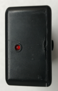
The IR LED is mounted with the 5mm holder in a 1/4 inch hole toward the top of the plastic cover. The depth of this holder will keep the IR LED flush with the box cover and help to narrow the beam a little. The heartbeat LED is mounted with the 3mm holder in a 5/32 inch hole in the top of the enclosure.
![]()
![]()
![]()
The completed circuit board slides into the slots at the top of the enclosure. If you’re using another enclosure that doesn’t have slots, you can use another piece of double-sided tape to affix the board to the back of the enclosure as well.
![]()
Wrapping It Up
Similar to Justin’s build, the parts come in at around $8, including the jumper wires, small strip of double-stick tape and small wire nuts. This was my first time using a PIC MCU, and luckily I was able to borrow my neighbor’s ICD 3 In-Circuit Debugger to program the chip and debug the code, so I didn’t have that added expense.
I tested the low-voltage detection code using my Rigol power supply, lowering the supply voltage from 2.05V by 0.01V and waiting the 5 cycles each time until the LED double-flashed. This consistently happened at 2.00 – 2.01V. I was expecting it to happen at 1.99V, but I don’t know how precise the power supply and ADC are down to hundredths of a volt.
With the new IR on/off timings, my Roomba does a quick about-face as soon as it reaches the beam. I’ve also seen the Roomba it do its “corner detection dance” at the virtual wall (those of you that have a Roomba know what I’m talking about) and it turned away every time, where the old timings would sometimes allow it to break through.
The DIY unit doesn’t have the “halo mode” that the OEM units have, but the wall mode works for the additional areas that I have so that’s not an issue. Halo mode uses an upward-facing IR LED pointed at a conical reflector to cast the IR beam in a circle pattern around the device. This might be an opportunity for a “Version 2” using a 3D printer and some mirror-finish paint.
http://gregthielen.me/blogstuff/2017/06/27/roomba-virtual-wall/
DIY Roomba Virtual Wall相关推荐
- DIY Virtual Wall for Roomba – Part One
Last weekend, we finally decided it was time to get a Roomba robotic vacuum. This decision was made ...
- 擦地机器人排行榜_拖地扫地机器人十大品牌排行榜哪个牌子好
繁忙的工作生活已让人疲惫不堪,更多人选择回家里寻找那份业余闲适.国家旅游局也曾在2013年发布一份报告指出,我国国民工作日的休闲时间仅占24小时的13.15%,相当于3小时.这3小时也包含了进餐和午休 ...
- 寿命长性价比高的室内扫地机器人SLAM导航方案
SLAM历史介绍 "舟师识地理,夜则观星,昼则观日,阴晦观指南针",几个世纪以前的古人便利用观星术和指南针实现了大航海中位置和航向的标定,走出世代居住的大陆走向广袤的大海,探索新大 ...
- 设计模式之C#实现--FactoryMethod
作者:cuike519的专栏 http://blog.csdn.net/cuike519/ 工厂方法的目的很明确就是定义一个用来创建对象的接口,但是他不直接创建对象,而由他的子类来创建,这样一来就 ...
- 深度技术GHOSTXP八分钟快速装机版 V3.5 (FAT32/NTFS两个版本HTTP BT 发布啦)
深度技术GHOSTXP八分钟快速装机版 V3.5 (FAT32/NTFS两个版本HTTP BT 发布啦) 深度Ghost XP 快速装机版3.5_八分钟装机板 此次制作的版本 我们自己经过多次的测试 ...
- 设计模式之原型法(ProtoType)----对象创建型模式
设计模式之原型法(ProtoType)----对象创建型模式 1.意图 用原型实例指定创建对象的种类,并且通过拷贝这些原型创建新的对象. 2.适用性 1)当要实例化的类是在运行时刻指定时,例如,通过动 ...
- Docker 安全问题与防护 (学习笔记)
文章目录 1. Docker面临的安全问题 1.1 Docker简介 1.2 Docker安全问题 2. Docker安全方案 2.1 Docker安全基线 2.2 Docker安全规则 2.3 Do ...
- [Robot projection]step5:机器人远程网站ROBOTWEBTOOLS
文章目录 前言 准备工作 机器人(内容待订正) 虚拟墙 服务器 端口问题 Tomcat问题 网站搭建 总结 前言 本文将使用ROBOTWEBTOOLS团队编写的代码包进行机器人远程控制网页的搭建,其团 ...
- wordpress 插件_适用于您的网站的2015年顶级WordPress安全插件
wordpress 插件 WordPress is the most used CMS as compared to any other CMS. The code behind WordPress ...
最新文章
- 中国自动驾驶技术有多强?你可能还不知道
- (超级详细)jit的介绍和用法
- 转:python模块学习 ---- smtplib 邮件发送
- 对于并列的TextField实现同步控制
- 收集一些jQueryMobile的插件和案例
- 威纶通触摸屏上传错误_威伦触摸屏程序上传方式
- NAS设备之NFS文件配置
- git如何查看缓存区文件内容_[暂存盘已满怎么解决]git暂存区的理解
- RPGMakerMV学习笔记(二)—— 制作第一个RPG游戏
- python将横转为竖_【后端开发】python数据竖着怎么变横的?
- 微信小店二次开发_微信小店二次开发功能套餐列表
- rust队友开挂_腐蚀RUST判断开挂玩家方法说明 怎么识别玩家是否外挂
- 其实你对三维设计一点也不陌生,这些竟然都属于它!
- 对比Excel,利用pandas进行数据分析各种用法
- 如何开发一个黑白照片还原成彩色,AI黑白图像图片上色系统毕业设计毕设作品
- CSDN什么时候倒闭啊
- “莫装B,装B遭雷劈”的英语翻译竞赛
- 用javascript实现图片的切换
- 从Eigen向量化谈内存对齐
- 无法加载播放器,请删除浏览器缓存后重试