在 iPad 上试验从用算法生成法线贴图-到法线映射光照效果
2019独角兽企业重金招聘Python工程师标准>>> 
在 iPad 上试验从用算法生成法线贴图-到法线映射光照效果
目录
概述
一般来说, 法线贴图是用高模的法线图, 低模的纹理图, 来生成较好的渲染效果. 而法线图通常是通过图像处理软件来生成的, 这里我们准备尝试用程序来生成法线图, 输入只有纹理图, 没有高度图.
那么这种方法究竟可行不可行? 答案是可行, 例如比较受欢迎的 CrazyBump 就是直接通过算法以纹理贴图未输入生成法线图, 不过具体算法就不清楚了, 接下来我们会进行各种试验, 来看看如何用算法生成能达到专业图像处理软件生成水准的法线图.
第一次脑洞
在对法线图有一点印象后, 我们打算先把纹理贴图转换为灰度图, 可以很明确地表示贴图表面的明暗程度, 再把灰度值转换为高度值--也就是z值(相当于高度图), 再利用原来的 x,y 坐标一起生成空间的向量坐标, 再求出该向量坐标对应的法线向量, 然后利用该法线向量生成法线图.
目前的问题是 z 值相对于 xy值有些太小, 所以把 xy 值缩小 2000 倍, 可以得到一张类似于法线图的蓝紫色图片, 但是跟实际的法线图对比, 还是不够好.
这个算法用 OpenGL ES Shader 实现, 主要是为了充分利用 GPU 来提高绘图速度, 代码如下:
-- 用来生成法线图的 shader
genNormal = {
vs = [[
attribute vec4 position;
attribute vec4 color;
attribute vec2 texCoord;varying vec2 vTexCoord;
varying vec4 vColor;
varying vec4 vPosition;uniform mat4 modelViewProjection;void main()
{vColor = color;vTexCoord = texCoord;vPosition = position;gl_Position = modelViewProjection * position;
}
]],
fs = [[
precision highp float;varying vec2 vTexCoord;
varying vec4 vColor;
varying vec4 vPosition;uniform sampler2D texture;// 纹理贴图
uniform sampler2D tex;
void main()
{//Sample the texture at the interpolated coordinatelowp vec4 col = texture2D( texture, vTexCoord );// vec4 normal = normalize(col.rgba);//彩色法线效果. 法向图// gl_FragColor = vec4(fmod( (normal.xyz+1.)/2.,1.0), 1.);// 先求像素点的灰度值float grey = 0.2126*col.r + 0.7152* col.g + 0.0722*col.b;//把范围为 [0, 1.0] 的颜色值变换为范围为 [-1.0, 1.0] 的法线值vec3 pos3D = vec3(vPosition.x, vPosition.y, grey);vec3 greyCol = vec3(grey,grey,grey);// 把灰度值作为 z 轴坐标, 组合出立体空间的 vec3 坐标//vec3 normal = normalize(vec3(vPosition.x*2.-1., vPosition.y*2.-1., grey*2.-1.));vec3 normal = normalize(vec3(vPosition.x/10000., vPosition.y/10000., grey*2.-1.));// 直接使用灰度图gl_FragColor = vec4(greyCol, col.a);gl_FragColor = vec4((normal.xyz+1.)/2., col.a);//Set the output color to the texture color// gl_FragColor = col;
}
]]
}
这个算法纯粹是偷懒(开始时不想认真研究法线图)+自由脑洞的产物, 效果奇差, 就不贴图了.
- 本次试验得到的经验: 以上代码是在对法线图一知半解的情况下脑洞大开写出来的, 在深入了解法线图的原理后, 就会发现这么去写纯粹是瞎搞, 而且居然一开始就作死直接用
shader写, 虽然最终跑起来了, 但是调试过程简直是欲仙欲死.
- 所以结论: 1.先好好研究明白法线图的概念原理, 再继续试验; 2.为了提高调试效率, 后续代码一律先在
CPU上跑, 跑通了再改写成shader代码.
用索贝尔算子计算xy法矢量
经过一番研究, 本次试验用 sobel operator 来实现
LUA算法实现
吸取上次的教训, 先写 CPU 代码如下:
-- 法线图生成函数:从高度图(灰度图)生成
-- 确保像素点坐标落在纹理贴图内: (1, pMax)
function clamp(pX, pMax)if (pX > pMax) thenreturn pMax;elseif (pX < 1) thenreturn 1;elsereturn pX;end
end-- 像素点光强度: 高度
function intensity(col)-- 计算像素点的灰度值--local average = (col.r + col.g + col.b)/3;local average = 0.3*col.r + 0.59*col.g + 0.11*col.breturn average
end-- 把单位向量从 [-1.0, 1.0] 转换范围到 [0,255]
function normal2Color(p)return (p + vec3(1.0,1.0,1.0)) * (255.0 / 2.0)
end-- 灰度图生成函数: (原始纹理贴图,强度)
function genGreyMap(img, s)local t = image(img.width, img.height)for y =1,img.height dofor x = 1,img.width dolocal r,g,b,a = img:get(x,y)local g = (0.3*r+0.59*g+0.11*b) * ( s or 1) t:set(x,y,color(g,g,g,255))        endendreturn t
end-- 根据灰度图生成法线图
function greyNormal(img,s)local w,h = img.width,img.heightlocal temp = image(w,h)for y =1,img.height dofor x = 1,img.width do-- 取得周围的像素点的 rgba值(灰度值)topLeft  = color(img:get(clamp( x - 1, w), clamp(y + 1, h)))top      = color(img:get(clamp( x , w), clamp(y + 1, h)))topRight = color(img:get(clamp( x + 1, w), clamp(y + 1, h)))right    = color(img:get(clamp( x + 1, w), clamp(y , h)))bottomRight    = color(img:get(clamp( x + 1, w), clamp(y - 1 , h)))bottom    = color(img:get(clamp( x , w), clamp(y - 1 , h)))bottomLeft    = color(img:get(clamp( x - 1, w), clamp(y - 1 , h)))left    = color(img:get(clamp( x - 1, w), clamp(y , h)))-- sobel filterdX = (topRight.r + 2.0 * right.r + bottomRight.r) - (topLeft.r + 2.0 * left.r + bottomLeft.r);dY = (bottomLeft.r + 2.0 * bottom.r + bottomRight.r) - (bottomLeft.r + 2.0 * top.r + topRight.r);dZ = 255 / s;newCol = normal2Color(vec3(dX,dY,dZ):normalize()) temp:set(x,y,color(newCol.x, newCol.y, newCol.z, 255))endendreturn temp
end
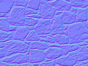
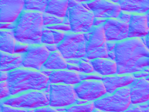
生成效果如下:
左边是本算法生成的法线图, 右边是使用图像处理软件得到的法线图:
光照效果, 使用算法生成的法线图 
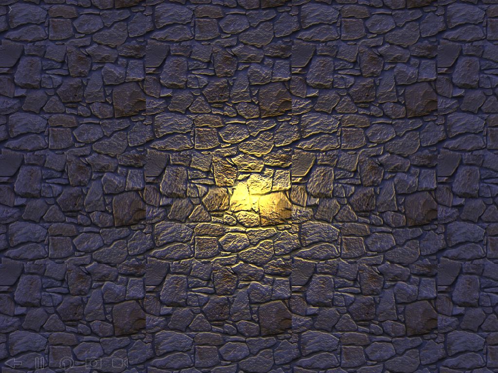
光照效果, 使用图像处理软件生成的法线图:


跟图像处理软件生成的法线图比较, 发现虽然用上述算法生成的法线图更真实地反映了纹理的表面细节情况, 但是在做法线映射时, 出现的立体效果反而不如经过图像处理软件修饰的法线图, 它把边缘扩散了,边缘部分看起来更光滑, 光线照射起来凸凹感更强.
不过还是希望能达到图像处理软件那种效果, 为此还专门发了一个求助帖根据纹理贴图生成法线图的算法, 如何改进? 感觉更像凹凸图, 结果还没等回应就被N多的新问题被冲得没影了...
shader算法实现
上述算法生成的法线图凑乎还能看, 不过就是生成速度太慢了, 一张 300*225 大小的纹理, 在我的 iPad2 上要跑10秒左右.
既然算法确定了, 那我们就可以放心地把它改写到 GPU 上去了, 结果半小时不到就搞定移植, 看来只要方法对头了, 效率自然就高, shader 代码如下:
-- 用 sobel 算子生成法线图    generate normal map with sobel operator
genNormal1 = {
vs = [[
attribute vec4 position;
attribute vec4 color;
attribute vec2 texCoord;varying vec2 vTexCoord;
varying vec4 vColor;
varying vec4 vPosition;uniform mat4 modelViewProjection;void main()
{
vColor = color;
vTexCoord = texCoord;
vPosition = position;
gl_Position = modelViewProjection * position;
}
]],
fs = [[
precision highp float;varying vec2 vTexCoord;
varying vec4 vColor;
varying vec4 vPosition;// 纹理贴图
uniform sampler2D tex;
uniform sampler2D texture;//图像横向长度-宽度, 图像纵向长度-高度
uniform float w;
uniform float h;float clamp1(float, float);
float intensity(vec4);float clamp1(float pX, float pMax) {if (pX > pMax) return pMax;else if (pX < 0.0)return 0.0;elsereturn pX;
}float intensity(vec4 col) {// 计算像素点的灰度值return 0.3*col.x + 0.59*col.y + 0.11*col.z;
}void main() {
// 横向步长-每像素点宽度,纵向步长-每像素点高度
float ws = 1.0/w ;
float hs = 1.0/h ;
float c[10];
vec2 p = vTexCoord;
lowp vec4 col = texture2D( texture, p );// sobel operator
// position.      Gx.            Gy
// 1 2 3     |-1. 0. 1.|   |-1. -2. -1.|
// 4 5 6     |-2. 0. 2.|   | 0.  0.  0.|
// 7 8 9     |-1. 0. 1.|   | 1.  2.  1.|
// 右上角,右,右下角
c[3] = intensity(texture2D( texture, vec2(clamp(p.x+ws,0.,w), clamp(p.y+hs,0.,h) )));
c[6] = intensity(texture2D( texture, vec2(clamp1(p.x+ws,w), clamp1(p.y,h))));
c[9] = intensity(texture2D( texture, vec2(clamp1(p.x+ws,w), clamp1(p.y-hs,h))));// 上, 下
c[2] = intensity(texture2D( texture, vec2(clamp1(p.x,w), clamp1(p.y+hs,h))));
c[8] = intensity(texture2D( texture, vec2(clamp1(p.x,w), clamp1(p.y-hs,h))));// 左上角, 左, 左下角
c[1] = intensity(texture2D( texture, vec2(clamp1(p.x-ws,w), clamp1(p.y+hs,h))));
c[4] = intensity(texture2D( texture, vec2(clamp1(p.x-ws,w), clamp1(p.y,h))));
c[7] = intensity(texture2D( texture, vec2(clamp1(p.x-ws,w), clamp1(p.y-hs,h))));// 先进行 sobel 滤波, 再把范围从 [-1,1] 调整到 [0,1]
float dx = (c[3]+2.*c[6]+c[9]-(c[1]+2.*c[4]+c[7]) + 1.0) / 2.0;
float dy = (c[7]+2.*c[8]+c[9]-(c[1]+2.*c[2]+c[3]) + 1.0) / 2.0;
float dz = (1.0 + 1.0) / 2.0;gl_FragColor = vec4(vec3(dx,dy,dz), col.a);}
]]
}
写了才发现, 原来 OpenGL ES 2.0 里自带了一个 clamp 函数, 不过需要输入3个参数:pX, pMin, pMax, 跟我们的 clamp 差不多, 为了避免报错, 把我们的 clamp 改为 clamp1.
跑一遍, 速度提升了10倍以上, 不到1秒就生成法线图了. 看来以后写图像处理算法一定要充分发掘 GPU 的潜力.
OK, 第二个试验成功了, 接下来的目标是在这个基础上对边缘做进一步处理, 目测貌似灰度值膨胀算法可以试验一下, 先研究研究再说.
下面是完整源代码:
-- normal mapping
--[[
The Normal Mapping code from Author: @1980geeksquad
Link: https://codea.io/talk/discussion/4674/example-of-normal-mapping
法线贴图光照效果的代码来自 @1980geeksquad
--]]function setup()displayMode(OVERLAY)-- 用 shader 生成法线图m1=mesh()m1Tex = readImage("Dropbox:n1")m1.shader=shader(shaders["genNormal1"].vs,shaders["genNormal1"].fs)m1.shader.texture = m1Texm1.shader.w, m1.shader.h = m1Tex.width, m1Tex.height   -- 单独显示由 shader 生成的法线图m1:addRect(m1Tex.width/2,m1Tex.height/2, m1Tex.width, m1Tex.height)-- 用 nMap 保存由 shader 生成的法线图nMap = image(m1Tex.width, m1Tex.height )setContext(nMap)m1:draw()setContext()    -- 用 shader 演示法线贴图-法线映射m = mesh()img = readImage("Dropbox:n1")m.shader=shader(shaders["NormalMapping"].vs,shaders["NormalMapping"].fs)local w,h = img.width, img.heightlocal ws,hs=WIDTH/w, HEIGHT/h--ws,hs = 1,1m.shader.Resolution = vec2(ws,hs)m.shader.LightPos = vec3(0,0,0.075)m.shader.LightColor = vec4(0.94,0.77,0.17,0.9)m.shader.AmbientColor = vec4(0.6,0.6,1.0,0.5)m.shader.Falloff = vec3(0.4,2.0,10.0)    m:setRectTex(m:addRect(WIDTH/2,HEIGHT/2,WIDTH,HEIGHT),0,0,ws,hs)-- the same as above line 手工定义顶点   -- m.vertices={vec2(0,0),vec2(WIDTH,0),vec2(0,HEIGHT),vec2(WIDTH,0),vec2(0,HEIGHT),vec2(WIDTH,HEIGHT) }-- m.texCoords = {vec2(0,0),vec2(ws,0),vec2(0,hs),vec2(ws,0),vec2(0,hs),vec2(ws,hs)}m.shader.tex = "Dropbox:n1"m.shader.s_multitex = "Dropbox:n2"m.shader.s_multitex = nMap--[[bumpImg = genBumpMap(img,0.007)greyImg = genGreyMap(img,1)--nMap = genNormalMap(img, 0.8)gnMap = greyNormal(greyImg,2)-- m.shader.tex = imgm.shader.s_multitex = gnMap--saveImage("Dropbox:grey1",greyImg)--saveImage("Dropbox:nmap1",gnMap)--]]tchx=0tchy=0
endfunction draw()background(0)-- 设置光源位置坐标m.shader.LightPos = vec3(tchx/WIDTH,tchy/HEIGHT,0.015)m:draw()--[[m1:draw()sprite(bumpImg,WIDTH/2+300,400)sprite(greyImg,WIDTH/2+300,150)--sprite(nMap,WIDTH/2,450)sprite(gnMap,WIDTH/2+350,650)sprite("Dropbox:n2",WIDTH/2,650)--]]sprite(nMap,WIDTH/2,650)
endfunction touched(touch)if touch.state == BEGAN or touch.state == MOVING thentchx=touch.x+50tchy=touch.y+50end
end-- 法线图生成函数:从高度图(灰度图)生成
-- 确保像素点坐标落在纹理贴图内: (1, pMax)
function clamp(pX, pMax)if (pX > pMax) thenreturn pMax;elseif (pX < 1) thenreturn 1;elsereturn pX;end
end-- 像素点光强度: 高度
function intensity(col)-- 计算像素点的灰度值--local average = (col.r + col.g + col.b)/3;return 0.3*col.r + 0.59*col.g + 0.11*col.b
end-- 把单位向量从 [-1.0, 1.0] 转换范围到 [0,255]
function normal2Color(p)return (p + vec3(1,1,1)) * (255 / 2)
end-- 直接从纹理贴图生成法线图
function genNormalMap(img,s)local w,h = img.width,img.heightlocal temp = image(w,h)for y =1,img.height dofor x = 1,img.width do-- 取得周围的像素点的 rgba值(灰度值-亮度)topLeft  = color(img:get(clamp( x - 1, w), clamp(y + 1, h)))top      = color(img:get(clamp( x , w), clamp(y + 1, h)))topRight = color(img:get(clamp( x + 1, w), clamp(y + 1, h)))right    = color(img:get(clamp( x + 1, w), clamp(y , h)))bottomRight    = color(img:get(clamp( x + 1, w), clamp(y - 1 , h)))bottom    = color(img:get(clamp( x , w), clamp(y - 1 , h)))bottomLeft    = color(img:get(clamp( x - 1, w), clamp(y - 1 , h)))left    = color(img:get(clamp( x - 1, w), clamp(y , h)))-- 计算得到灰度值tl = intensity(topLeft)t = intensity(top);tr = intensity(topRight);r = intensity(right);br = intensity(bottomRight);b = intensity(bottom);bl = intensity(bottomLeft);l = intensity(left);--滤波 sobel filterdX = (tr + 2.0 * r + br) - (tl + 2.0 * l + bl);dY = (bl + 2.0 * b + br) - (tl + 2.0 * t + tr);dZ = 255 / s;newCol = normal2Color(vec3(dX,dY,dZ))newCol = normal2Color(vec3(dX,dY,dZ):normalize())--print(newCol)temp:set(x,y,color(newCol.x, newCol.y, newCol.z, 255))endendreturn tempend-- 从灰度图生成法线图
function greyNormal(img,s)local w,h = img.width,img.heightlocal temp = image(w,h)local sobel = math.sqrt(2.0)local sobel = 1.0for y =1,img.height dofor x = 1,img.width do-- 取得 me 周围的像素点的 rgba值(灰度值)tl  = color(img:get(clamp( x - 1, w), clamp(y + 1, h)))t   = color(img:get(clamp( x , w), clamp(y + 1, h)))tr  = color(img:get(clamp( x + 1, w), clamp(y + 1, h)))r   = color(img:get(clamp( x + 1, w), clamp(y , h)))br  = color(img:get(clamp( x + 1, w), clamp(y - 1 , h)))b   = color(img:get(clamp( x , w), clamp(y - 1 , h)))bl  = color(img:get(clamp( x - 1, w), clamp(y - 1 , h)))l   = color(img:get(clamp( x - 1, w), clamp(y , h)))me  = color(img:get(clamp( x , w), clamp(y , h)))--滤波 sobel filterdX = (tr.r + sobel * r.r + br.r) - (tl.r + sobel * l.r + bl.r)dY = (bl.r + sobel * b.r + br.r) - (tl.r + sobel * t.r + tr.r)dZ = 255 / snewCol = normal2Color(vec3(dX,dY,dZ):normalize())--print(newCol)temp:set(x,y,color(newCol.x, newCol.y, newCol.z, 255))endendreturn temp
end-- 灰度图生成函数
function genGreyMap(img, s)local t = image(img.width, img.height)for y =1,img.height dofor x = 1,img.width dolocal r,g,b,a = img:get(x,y)local g = (0.3*r+0.59*g+0.11*b)*st:set(x,y,color(g,g,g,255))endendreturn t
end-- 各种贴图效果 shader
shaders = {
--normal mapping
NormalMapping = { vs=[[
//--------vertex shader---------
attribute vec4 position;
attribute vec4 color;
attribute vec2 texCoord;varying vec2 vTexCoord;
varying vec4 vColor;uniform mat4 modelViewProjection;void main()
{
vColor = color;
vTexCoord = texCoord;
gl_Position = modelViewProjection * position;
}
]],
fs=[[
//---------Fragment shader------------
//Default precision qualifier
precision highp float;varying vec2 vTexCoord;
varying vec4 vColor;// 纹理贴图
uniform sampler2D tex;
// 对应的法向图
uniform lowp sampler2D s_multitex;uniform vec2 Resolution;
uniform vec3 LightPos;
uniform vec4 LightColor;
uniform vec4 AmbientColor;
uniform vec3 Falloff;void main()
{
//vec4 DiffuseColor = texture2D(tex,vTexCoord);
//vec3 NormalMap = texture2D(s_multitex,vTexCoord).rgb;
vec4 DiffuseColor = texture2D(tex,vec2(mod(vTexCoord.x,1.0), mod(vTexCoord.y,1.0)));
vec3 NormalMap = texture2D(s_multitex,vec2(mod(vTexCoord.x,1.0), mod(vTexCoord.y,1.0))).rgb;
//NormalMap.g = 1.0 - NormalMap.g;
vec3 LightDir = vec3(LightPos.xy-(vTexCoord.xy/Resolution.xy),LightPos.z);
LightDir.x *= Resolution.x/Resolution.y;
float D = length(LightDir);
vec3 N = normalize(NormalMap*2.0-1.0);
vec3 L = normalize(LightDir);
vec3 Diffuse = (LightColor.rgb * LightColor.a) * max(dot(N,L), 0.0);
vec3 Ambient = AmbientColor.rgb * AmbientColor.a;
float Attenuation = 1.0 / (Falloff.x + (Falloff.y*D) + (Falloff.z*D*D));
// 亮度 = 环境光 + 散射 * 衰减
vec3 Intensity = Ambient + Diffuse * Attenuation;
vec3 FinalColor = DiffuseColor.rgb * Intensity;
gl_FragColor = vColor * vec4(FinalColor,DiffuseColor.a);
}
]]},-- 旧的用来生成法向图的 shader
genNormal = {
vs = [[
attribute vec4 position;
attribute vec4 color;
attribute vec2 texCoord;varying vec2 vTexCoord;
varying vec4 vColor;
varying vec4 vPosition;uniform mat4 modelViewProjection;void main()
{
vColor = color;
vTexCoord = texCoord;
vPosition = position;
gl_Position = modelViewProjection * position;
}
]],
fs = [[
precision highp float;varying vec2 vTexCoord;
varying vec4 vColor;
varying vec4 vPosition;uniform sampler2D texture;// 纹理贴图
uniform sampler2D tex;
void main()
{
//Sample the texture at the interpolated coordinate
lowp vec4 col = texture2D( texture, vTexCoord );// vec4 normal = normalize(col.rgba);
//彩色法线效果. 法向图
// gl_FragColor = vec4(fmod( (normal.xyz+1.)/2.,1.0), 1.);// 先求像素点的灰度值
float grey = 0.2126*col.r + 0.7152* col.g + 0.0722*col.b;
//把范围为 [0, 1.0] 的颜色值变换为范围为 [-1.0, 1.0] 的法线值vec3 pos3D = vec3(vPosition.x, vPosition.y, grey);
vec3 greyCol = vec3(grey,grey,grey);// 把灰度值作为 z 轴坐标, 组合出立体空间的 vec3 坐标
//vec3 normal = normalize(vec3(vPosition.x*2.-1., vPosition.y*2.-1., grey*2.-1.));
vec3 normal = normalize(vec3(vPosition.x/1000., vPosition.y/1000., grey*2.-1.));// 直接使用灰度图
gl_FragColor = vec4(greyCol, col.a);gl_FragColor = vec4((normal.xyz+1.)/2., col.a);//Set the output color to the texture color
// gl_FragColor = col;
}
]]
},-- 用 sobel 算子生成法线图    generate normal map with sobel operator
genNormal1 = {
vs = [[
attribute vec4 position;
attribute vec4 color;
attribute vec2 texCoord;varying vec2 vTexCoord;
varying vec4 vColor;
varying vec4 vPosition;uniform mat4 modelViewProjection;void main()
{
vColor = color;
vTexCoord = texCoord;
vPosition = position;
gl_Position = modelViewProjection * position;
}
]],
fs = [[
precision highp float;varying vec2 vTexCoord;
varying vec4 vColor;
varying vec4 vPosition;// 纹理贴图
uniform sampler2D tex;
uniform sampler2D texture;//图像横向长度-宽度, 图像纵向长度-高度
uniform float w;
uniform float h;float clamp1(float, float);
float intensity(vec4);float clamp1(float pX, float pMax) {if (pX > pMax) return pMax;else if (pX < 0.0)return 0.0;elsereturn pX;
}float intensity(vec4 col) {// 计算像素点的灰度值return 0.3*col.x + 0.59*col.y + 0.11*col.z;
}void main() {
// 横向步长-每像素点宽度,纵向步长-每像素点高度
float ws = 1.0/w ;
float hs = 1.0/h ;
float c[10];
vec2 p = vTexCoord;
lowp vec4 col = texture2D( texture, p );// sobel operator
// position.      Gx.            Gy
// 1 2 3     |-1. 0. 1.|   |-1. -2. -1.|
// 4 5 6     |-2. 0. 2.|   | 0.  0.  0.|
// 7 8 9     |-1. 0. 1.|   | 1.  2.  1.|
// 右上角,右,右下角
c[3] = intensity(texture2D( texture, vec2(clamp(p.x+ws,0.,w), clamp(p.y+hs,0.,h) )));
c[6] = intensity(texture2D( texture, vec2(clamp1(p.x+ws,w), clamp1(p.y,h))));
c[9] = intensity(texture2D( texture, vec2(clamp1(p.x+ws,w), clamp1(p.y-hs,h))));// 上, 下
c[2] = intensity(texture2D( texture, vec2(clamp1(p.x,w), clamp1(p.y+hs,h))));
c[8] = intensity(texture2D( texture, vec2(clamp1(p.x,w), clamp1(p.y-hs,h))));// 左上角, 左, 左下角
c[1] = intensity(texture2D( texture, vec2(clamp1(p.x-ws,w), clamp1(p.y+hs,h))));
c[4] = intensity(texture2D( texture, vec2(clamp1(p.x-ws,w), clamp1(p.y,h))));
c[7] = intensity(texture2D( texture, vec2(clamp1(p.x-ws,w), clamp1(p.y-hs,h))));// 先进行 sobel 滤波, 再把范围从 [-1,1] 调整到 [0,1]
float dx = (c[3]+2.*c[6]+c[9]-(c[1]+2.*c[4]+c[7]) + 1.0) / 2.0;
float dy = (c[7]+2.*c[8]+c[9]-(c[1]+2.*c[2]+c[3]) + 1.0) / 2.0;
float dz = (1.0 + 1.0) / 2.0;gl_FragColor = vec4(vec3(dx,dy,dz), col.a);}
]]
}
}
Xcode 项目链接(等有空了再输出, 先占个位)
参考
example-of-normal-mapping ShaderLesson6 can-normal-maps-be-generated-from-a-texture
转载于:https://my.oschina.net/freeblues/blog/665251
在 iPad 上试验从用算法生成法线贴图-到法线映射光照效果相关推荐
- Ipad上选择专业好用的思维导图软件
在iPad 上如何选择思维导图工具?评价一款应用APP是否好用,除了软件自身的功能,很大程度上也取决于用户的体验度.按照东尼博赞的理论,手写的思维导图更有益于人的记忆,但是在实际工作.生活中,对于思维 ...
- 亿图AI助手一键生成思维导图,捕捉万千灵感,快速出彩!
短短几个月,AIGC(AI-Generated Content)人工智能生成内容,就像一场惊涛骇浪席卷了全球,AIGC会改变人类创作者与工具之间的协作关系,形成新的分工方式. 不久前,亿图软件上线了一 ...
- java自动生成略缩图
当你要做一个图库的项目时,对图片大小.像素的控制是首先需要解决的难题. 本篇文章,在前辈的经验基础上,分别对单图生成略缩图和批量生成略缩图做个小结. 一.单图生成略缩图 单图经过重新绘制,生成新的图片 ...
- 线上使用雪花算法生成id重复问题
项目中使用的是hutool工具类库提供的雪花算法生成id方式,版本使用的是5.3.1 <dependency><groupId>cn.hutool</groupId> ...
- php hmacsha1计算,PHP HMAC_SHA1 算法 生成算法签名
HMAC_SHA1(Hashed Message Authentication Code, Secure Hash Algorithm)是一种安全的基于加密hash函数和共享密钥的消息认证协议. 它可 ...
- 计算机程序数据随机变化,计算机程序编程课程设计报告(马尔可夫链算法生成随机可读文本)...
<计算机程序编程课程设计报告(马尔可夫链算法生成随机可读文本)>由会员分享,可在线阅读,更多相关<计算机程序编程课程设计报告(马尔可夫链算法生成随机可读文本)(15页珍藏版)> ...
- 提升C语言程序运行效率 马尔可夫,计算机程序编程课程设计报告(马尔可夫链算法生成随机可读文本).doc...
PAGE 1 计算机程序编程课程设计报告 (马尔可夫链算法生成随机可读文本) 引言: 马尔可夫链的数学背景: 马尔可夫链,因安德烈?马尔可夫(A.A.Markov,1856-1922)得名 ,是数学随 ...
- 把激光雷达放在iPad上是怎样的体验?看到“测距仪”App的效果我震惊了
晓查 发自 凹非寺 量子位 报道 | 公众号 QbitAI 就在今天早晨,苹果发布了iOS/iPadOS 13.4更新,除了常规升级,还有个看似不起眼的更新:加入了ARKit 3.5. 如果你关注过 ...
- 根据twitter的snowflake算法生成唯一ID
C#版本 /// <summary>/// 根据twitter的snowflake算法生成唯一ID/// snowflake算法 64 位/// 0---0000000000 000000 ...
最新文章
- 企业网络推广方案分享如何针对大量的长尾词进行更好地优化方法!
- K8S部署工具:KubeOperator安装部署
- oracle 1g apex030200,APEX_030200
- gj5 自定义序列类
- 畅销书《深入浅出Vue.js》作者,在阿里淘系1年的收获成长
- cg word List 3
- 微信退款通知,退款回调数据解密.SHA256签名AEAD_AES_256_GCM解密
- C++ STL 遍历 map 的时候如何删除其中的 element
- 反射--获取当前子类父类的泛型类型
- 在GridView中加入单选按钮RadioButton
- 第一次请领导喝酒,五百左右的白酒有哪些推荐?
- 银行对公业务结构图梳理
- 经典公开课、好的学习网站
- php5.5 pdo mysql_PHP5中使用PDO连接数据库的方法
- 添加样式(后台给字段note(left,height-auto ))
- C语言函数程序实例(超全)
- 如何在Arduino上使用OV7670摄像头模块
- 为了背单词,我花了两天写了一款背单词小程序
- Focal Loss的阅读笔记
- Logo创作灵魂(下篇)
热门文章
- 解决mysql出现the table is full的问题
- 使用虚拟磁盘文件创建虚拟机
- 图像处理中的采样与量化
- 苹果手机描述文件服务器地址是什么,苹果手机设置里面有个描述文件是什么意思...
- mysql 组提交原理_图解MySQL | [原理解析] MySQL组提交(group commit)
- 怎样在百度地图上标注上自己公司的名称使别人能在搜索百度地图的同时在地图上能看见本公司地址?
- satis 搭建 Composer 私有库的方法
- Lammps中常用的势函数和晶体库资源收集
- 经营在线业务的首选客服工具--SS客服
- SMA TE: Semi-Supervised Spatio-Temporal RepresentationLearning on Multivariate Time Series