lorawan和lora_用于物联网的LoRa和LoRaWAN
lorawan和lora
介绍 (Introduction)
According to the LoRa Alliance, Low-Power, Wide-Area Networks (LPWAN) are projected to support a major portion of the billions of devices forecasted for the Internet of Things (IoT). LoRaWAN is designed from the bottom up to optimize LPWANs for battery lifetime, capacity, range, and cost. LoRa and LoRaWAN permit long-range connectivity for the Internet of Things (IoT) devices in different types of industries. According to Wikipedia, LoRaWAN defines the communication protocol and system architecture for the network, while the LoRa physical layer enables the long-range communication link.
根据LoRa联盟的说法 ,低功耗,广域网(LPWAN)预计将支持预计用于物联网(IoT)的数十亿设备的很大一部分。 LoRaWAN从下至上进行设计,以针对电池寿命,容量,范围和成本优化LPWAN。 LoRa和LoRaWAN允许在不同类型的行业中为物联网(IoT)设备提供远程连接。 根据Wikipedia的介绍 ,LoRaWAN定义了网络的通信协议和系统架构,而LoRa物理层实现了远程通信链接。
劳拉 (LoRa)
Long Range (LoRa), the low-power wide-area network (LPWAN) protocol developed by Semtech, sits at layer 1, the physical layer, of the seven-layer OSI model (Open Systems Interconnection model) of computer networking. The physical layer defines the means of transmitting raw bits over a physical data link connecting network nodes. LoRa uses license-free sub-gigahertz radio frequency (RF) bands, including 433 MHz, 868 MHz (Europe), 915 MHz (Australia and North America), and 923 MHz (Asia). LoRa enables long-range transmissions with low power consumption.
远程( LoRa )是Semtech开发的低功耗广域网(LPWAN)协议,位于计算机网络的七层OSI模型 (开放系统互连模型)的第1层,即物理层 。 物理层定义了通过连接网络节点的物理数据链路传输原始位的方法。 LoRa使用免许可的千兆赫兹射频(RF)频段,包括433 MHz,868 MHz(欧洲),915 MHz(澳大利亚和北美)和923 MHz(亚洲)。 LoRa可实现低功耗的远程传输。
广域网 (LoRaWAN)
LoRaWAN is a cloud-based medium access control (MAC) sublayer (layer 2) protocol but acts mainly as a network layer (layer 3) protocol for managing communication between LPWAN gateways and end-node devices as a routing protocol, maintained by the LoRa Alliance. The MAC sublayer and the logical link control (LLC) sublayer together make up layer 2, the data link layer, of the OSI model.
LoRaWAN是基于云的媒体访问控制(MAC)子层(第2层)协议,但主要用作网络层 (第3层)协议,用于管理LPWAN网关和终端节点设备之间的通信,作为路由协议,由LoRa维护联盟 。 MAC子层和逻辑链路控制(LLC)子层共同构成OSI模型的第2层,即数据链路层 。
LoRaWAN is often cited as having greater than a 10-km-wide coverage area in rural locations. However, according to other sources, it is generally more limited. According to the Electronic Design article, 11 Myths About LoRaWAN, a typical LoRaWAN network range depends on numerous factors-indoor or outdoor gateways, the payload of the message, the antenna used, etc. On average, in an urban environment with an outdoor gateway, you can expect up to 2- to 3-km-wide coverage, while in the rural areas it can reach beyond 5 to 7 km. LoRa’s range depends on the “radio line-of-sight.” Radio waves in the 400 MHz to 900 MHz range may pass through some obstructions, depending on their composition, but will be absorbed or reflected otherwise. This means that the signal can potentially reach as far as the horizon, as long as there are no physical barriers to block it.
LoRaWAN通常被认为在农村地区的覆盖范围超过10公里。 但是,根据其他消息来源,通常更受限制。 根据《电子设计》文章《 关于LoRaWAN的11个迷思》 , 典型的LoRaWAN网络范围取决于许多因素,包括室内或室外网关,消息的有效负载,使用的天线等。平均而言,在具有室外网关的城市环境中,您可以预期覆盖2至3公里,而在农村地区则可以覆盖5至7公里。 LoRa的范围取决于“无线电视线”。 400 MHz至900 MHz范围内的无线电波可能会穿过某些障碍物,具体取决于它们的成分,但是会被吸收或反射。 这意味着只要没有物理障碍将其阻挡,信号就可以潜在地到达地平线。
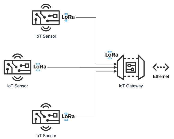
In the following hands-on post, we will explore the use of the LoRa and LoRaWAN protocols to transmit and receive sensor data, over a substantial distance, between an IoT device, containing a number of embedded sensors, and an IoT gateway.
在下面的动手文章中,我们将探索使用LoRa和LoRaWAN协议在包含大量嵌入式传感器的IoT设备与IoT网关之间在相当长的距离内发送和接收传感器数据。
推荐硬件 (Recommended Hardware)
For this post, I have used the following hardware.
在这篇文章中,我使用了以下硬件。
带有嵌入式传感器的物联网设备 (IoT Device with Embedded Sensors)
I have used an Arduino single-board microcontroller as an IoT sensor, actually an array of sensors. The 3.3V AI-enabled Arduino Nano 33 BLE Sense board (Amazon: USD 36.00), released in August 2019, comes with the powerful nRF52840 processor from Nordic Semiconductors, a 32-bit ARM Cortex-M4 CPU running at 64 MHz, 1MB of CPU Flash Memory, 256KB of SRAM, and a NINA-B306 stand-alone Bluetooth 5 low energy (BLE) module.
我已经将Arduino单板微控制器用作IoT传感器,实际上是一系列传感器。 于2019年8月发布的具有3.3V AI功能的Arduino Nano 33 BLE Sense板( 亚马逊 :36.00美元)配备了Nordic Semiconductors的功能强大的nRF52840处理器,运行于64 MHz的32位ARM Cortex-M4 CPU,1MB CPU闪存,256KB SRAM和NINA-B306独立式Bluetooth 5低功耗(BLE)模块。
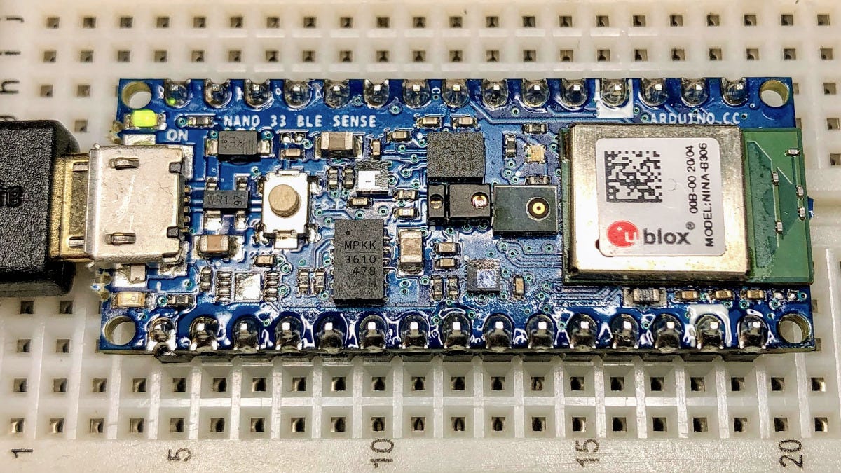
The Sense also contains an impressive array of embedded sensors:
Sense还包含一系列令人印象深刻的嵌入式传感器:
9-axis Inertial Sensor (LSM9DS1): 3D digital linear acceleration sensor, a 3D digital
9轴惯性传感器( LSM9DS1 ):3D数字线性加速度传感器,3D数字
angular rate sensor, and a 3D digital magnetic sensor
角速率传感器和3D数字磁传感器
Humidity and Temperature Sensor (HTS221): Capacitive digital sensor for relative humidity and temperature
湿度和温度传感器( HTS221 ):用于相对湿度和温度的电容式数字传感器
Barometric Sensor (LPS22HB): MEMS nano pressure sensor: 260–1260 hectopascal (hPa) absolute digital output barometer
气压传感器( LPS22HB ):MEMS纳米压力传感器:260–1260百帕斯卡(hPa)绝对数字输出气压计
Microphone (MP34DT05): MEMS audio sensor omnidirectional digital microphone
麦克风( MP34DT05 ):MEMS音频传感器全向数字麦克风
Gesture, Proximity, Light Color, and Light Intensity Sensor (APDS9960): Advanced Gesture detection, Proximity detection, Digital Ambient Light Sense (ALS), and Color Sense (RGBC).
手势,接近度,光色和光强度传感器( APDS9960 ):高级手势检测,接近度检测,数字环境光感(ALS)和色彩感(RGBC)。
The Arduino Sense is an excellent, low-cost single-board microcontroller for learning about the collection and transmission of IoT sensor data.
Arduino Sense是一款出色的低成本单板微控制器,可用于学习有关IoT传感器数据的收集和传输。
物联网网关 (IoT Gateway)
An IoT Gateway, according to TechTarget, is a physical device or software program that serves as the connection point between the Cloud and controllers, sensors, and intelligent devices. All data moving to the Cloud, or vice versa goes through the gateway, which can be either a dedicated hardware appliance or software program.
根据TechTarget的说法,IoT网关是一种物理设备或软件程序,充当Cloud与控制器,传感器和智能设备之间的连接点。 所有移至云的数据(反之亦然)都通过网关,网关可以是专用的硬件设备或软件程序。
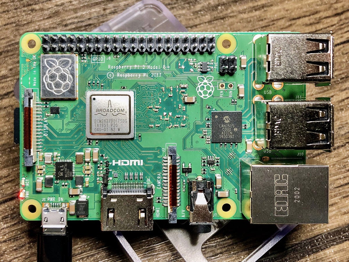
I have used an a third-generation Raspberry Pi 3 Model B+ single-board computer (SBC), to serve as an IoT Gateway. This Raspberry Pi model features a 1.4GHz Cortex-A53 (ARMv8) 64-bit quad-core processor System on a Chip (SoC), 1GB LPDDR2 SDRAM, dual-band wireless LAN, Bluetooth 4.2 BLE, and Gigabit Ethernet (Amazon: USD 42.99).
我已经使用了第三代Raspberry Pi 3 Model B +单板计算机(SBC)作为IoT网关。 该Raspberry Pi型号具有1.4GHz的Cortex-A53(ARMv8)64位四核处理器片上系统(SoC),1GB LPDDR2 SDRAM,双频无线LAN,蓝牙4.2 BLE和千兆以太网( Amazon :USD 42.99)。
To follow along with the post, you could substitute the Raspberry Pi for any Linux-based machine to run the included sample Python script.
在后续文章中,您可以将Raspberry Pi替换为任何基于Linux的机器,以运行随附的示例Python脚本。
LoRa收发器模块 (LoRa Transceiver Modules)
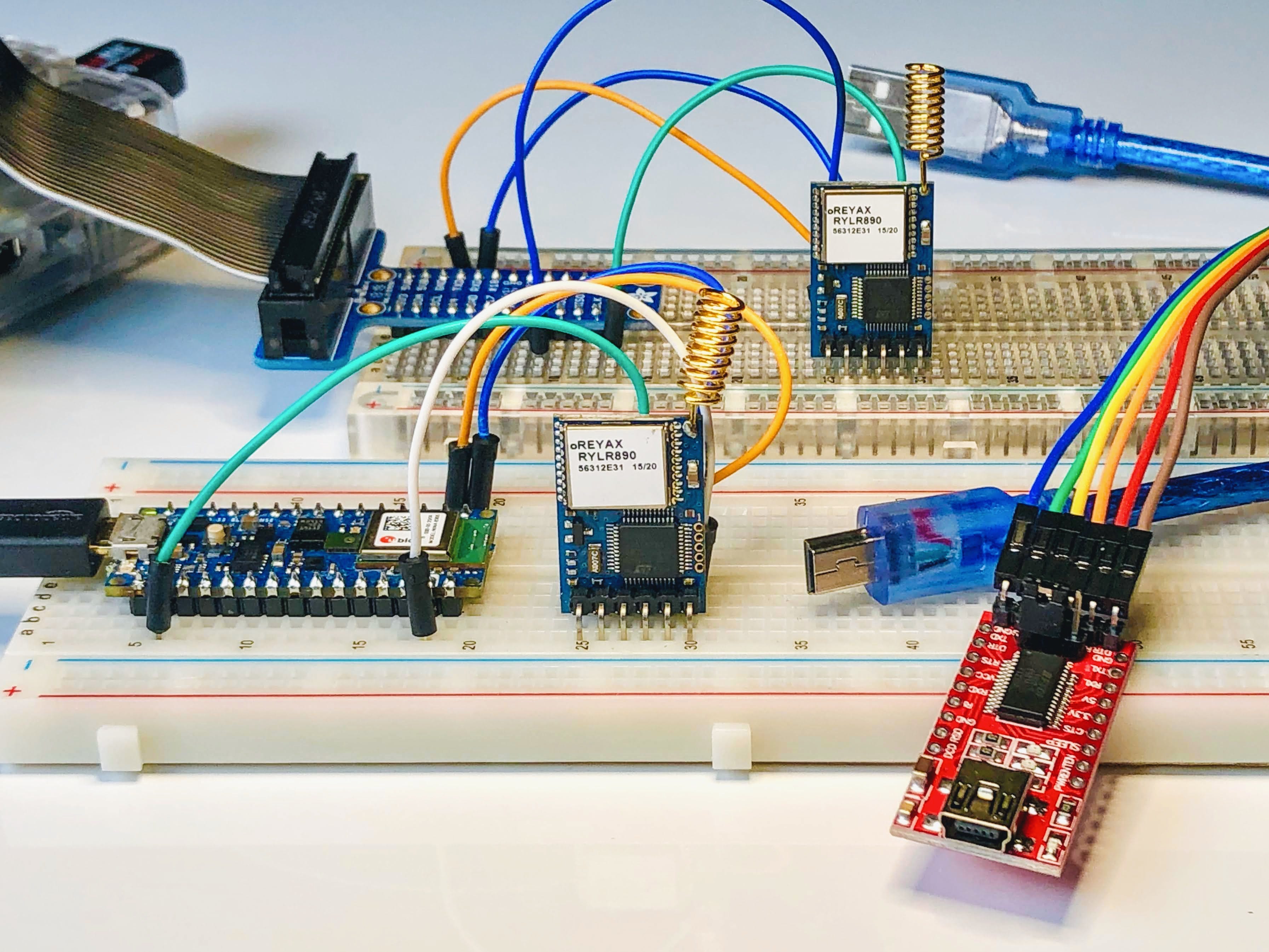
To transmit the IoT sensor data between the IoT device, containing the embedded sensors, and the IoT gateway, I have used the REYAX RYLR896 LoRa transceiver module (Amazon: USD 19.50 x 2). The transceiver modules are commonly referred to as a universal asynchronous receiver-transmitter (UART). A UART is a computer hardware device for asynchronous serial communication in which the data format and transmission speeds are configurable.
为了在包含嵌入式传感器的IoT设备和IoT网关之间传输IoT传感器数据,我使用了REYAX RYLR896 LoRa收发器模块( 亚马逊 :USD 19.50 x 2)。 收发器模块通常称为通用异步收发器 (UART)。 UART是用于异步串行通信的计算机硬件设备,其中数据格式和传输速度是可配置的。
According to the manufacturer, REYAX, the RYLR896 contains the Semtech SX1276 long-range, low power transceiver. The RYLR896 module provides ultra-long range spread spectrum communication and high interference immunity while minimizing current consumption. This transceiver operates at both the 868 and 915 MHz frequency ranges. We will be transmitting at 915 MHz for North America, in this post. Each RYLR896 module contains a small, PCB integrated, helical antenna.
根据制造商REYAX的说法, RYLR896包含Semtech SX1276远程低功耗收发器。 RYLR896模块提供超远距离扩频通信和高抗干扰性,同时将电流消耗降至最低。 该收发器在868和915 MHz频率范围内均可工作。 在这篇文章中,我们将以915 MHz的速度向北美进行传输。 每个RYLR896模块都包含一个小的PCB集成螺旋天线。
安全 (Security)
The RYLR896 is capable of the AES 128-bit data encryption. Using the Advanced Encryption Standard (AES), we will encrypt the data sent from the IoT device to the IoT gateway, using a 32 hex digit password (128 bits / 4 bits/hex digit = 32 hex digits). Using hexadecimal notation, the password is limited to digits 0–9 and characters A–F.
RYLR896能够进行AES 128位数据加密。 使用高级加密标准 (AES),我们将使用32位十六进制数字密码(128位/ 4位/十六进制数字= 32位十六进制数字)对从IoT设备发送到IoT网关的数据进行加密。 使用十六进制表示法,密码仅限于数字0–9和字符A–F。
USB转TTL串行转换器适配器 (USB to TTL Serial Converter Adapter)
Optionally, to configure, test, and debug the RYLR896 LoRa transceiver module directly from your laptop, you can use a USB to TTL serial converter adapter. I currently use the IZOKEE FT232RL FTDI USB to TTL Serial Converter Adapter Module for 3.3V and 5V (Amazon: USD 9.49 for 2). The 3.3V RYLR896 module easily connects to the USB to TTL Serial Converter Adapter using the TXD/TX, RXD/RX, VDD/VCC, and GND pins. We use serial communication to send and receive data through TX (transmit) and RX (receive) pins. The wiring is shown below: VDD to VCC, GND to GND, TXD to RX, and RXD to TX.
(可选)要直接从笔记本电脑配置,测试和调试RYLR896 LoRa收发器模块,可以使用USB到TTL串行转换器适配器。 我目前使用的是3.3V和5V的IZOKEE FT232RL FTDI USB转TTL串行转换器适配器模块( Amazon :2美元,9.49美元)。 3.3V RYLR896模块使用TXD / TX,RXD / RX,VDD / VCC和GND引脚轻松连接到USB至TTL串行转换器适配器。 我们使用串行通信通过TX(发送)和RX(接收)引脚发送和接收数据。 接线如下所示:VDD至VCC,GND至GND,TXD至RX,以及RXD至TX。
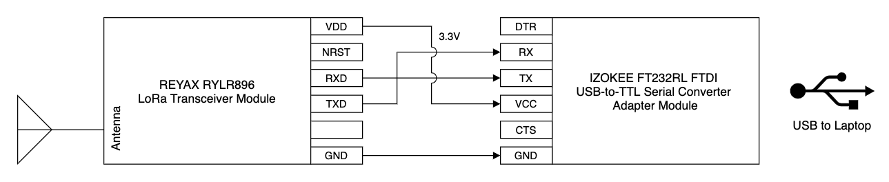
The FT232RL has support for baud rates up to 115,200 bps, which is the speed we will use to communicate with the RYLR896 module.
FT232RL支持高达115,200 bps的波特率,这是我们将用来与RYLR896模块通信的速度。
Arduino素描 (Arduino Sketch)
For those not familiar with Arduino, a sketch is the name that Arduino uses for a program. It is the unit of code that is uploaded into non-volatile flash memory and runs on an Arduino board. The Arduino language is a set of C and C++ functions. All standard C and C++ constructs supported by the avr-g++ compiler should work in Arduino.
对于不熟悉Arduino的人, 草图是Arduino在程序中使用的名称。 它是代码单元,已上传到非易失性闪存中并在Arduino板上运行。 Arduino语言是一组C和C ++函数。 avr-g ++编译器支持的所有标准C和C ++结构都应在Arduino中工作。
For this post, the sketch, lora_iot_demo.ino, contains all the code necessary to collect and securely transmit the environmental sensor data, including temperature, relative humidity, barometric pressure, RGB color, and ambient light intensity, using the LoRaWAN protocol. All code for this post, including the sketch, can be found on GitHub.
对于此帖子,草图lora_iot_demo.ino包含使用LoRaWAN协议收集和安全传输环境传感器数据所需的所有代码,包括温度,相对湿度,大气压力,RGB颜色和环境光强度。 这篇文章的所有代码(包括草图)都可以在GitHub上找到 。
AT指令 (AT Commands)
Communications with the RYLR896’s long-range modem is done using AT commands. AT commands are instructions used to control a modem. AT is the abbreviation of ATtention. Every command line starts with “AT”. That is why modem commands are called AT commands, according to Developer’s Home. A complete list of AT commands can be downloaded as a PDF from the RYLR896 product page.
使用AT命令与RYLR896的远程调制解调器进行通信。 AT命令是用于控制调制解调器的指令。 AT是ATtention的缩写。 每个命令行以“ AT”开头。 根据开发人员之家的说法,这就是为什么将调制解调器命令称为AT命令的原因 。 可以从RYLR896产品页面以PDF格式下载AT命令的完整列表。
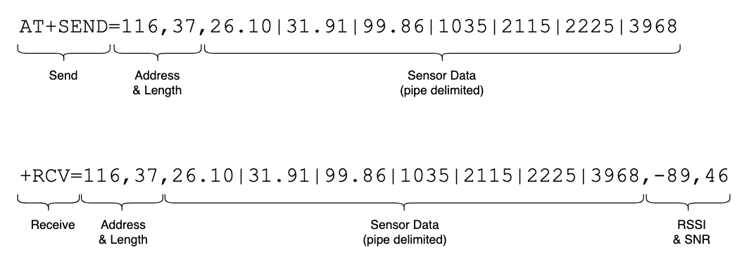
To efficiently transmit the environmental sensor data from the IoT sensor to the IoT gateway, the sketch concatenates the sensor values together in a single string. The string will be incorporated into AT command to send the data to the RYLR896 LoRa transceiver module. To make it easier to parse the sensor data on the IoT gateway, we will delimit the sensor values with a pipe (|), as opposed to a comma. The maximum length of the payload (sensor data) is 240 bytes.
为了有效地将环境传感器数据从IoT传感器传输到IoT网关,草图将传感器值连接到一个字符串中。 该字符串将合并到AT命令中,以将数据发送到RYLR896 LoRa收发器模块。 为了更轻松地解析IoT网关上的传感器数据,我们将使用管道(|)(而不是逗号)来分隔传感器值。 有效负载( 传感器数据 )的最大长度为240个字节。
Below, we see an example of an AT command used to send the sensor data from the IoT sensor and the corresponding unencrypted data received by the IoT gateway. Both strings contain the LoRa transmitter Address ID, payload length, and the payload. The data received by the IoT gateway also contains the Received signal strength indicator (RSSI), and Signal-to-noise ratio (SNR).
在下面,我们看到一个AT命令的示例,该命令用于从IoT传感器发送传感器数据以及由IoT网关接收的相应未加密数据。 这两个字符串都包含LoRa发送器地址ID,有效载荷长度和有效载荷。 物联网网关接收的数据还包含接收信号强度指示器 (RSSI)和信噪比 (SNR)。
配置,测试和调试 (Configure, Test, and Debug)
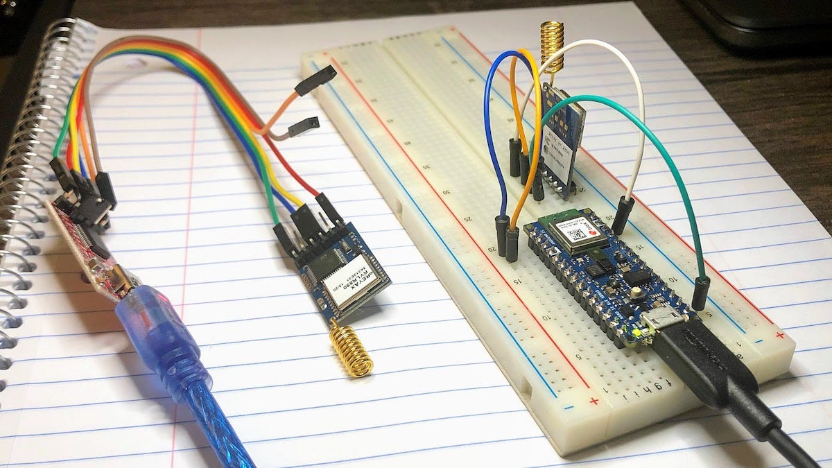
As discussed earlier, to configure, test, and debug the RYLR896 LoRa transceiver modules without the use of the IoT gateway, you can use a USB to TTL serial converter adapter. The sketch is loaded on the Arduino Sense (the IoT device) and actively transmits data through one of the RYLR896 modules (shown below right). The other RYLR896 module is connected to your laptop’s USB port, via the USB to TTL serial converter adapter (shown below left). Using a terminal and the screen command, or the Arduino desktop application’s Serial Terminal, we can receive the sensor data from the Arduino Sense.
如前所述,在不使用IoT网关的情况下配置,测试和调试RYLR896 LoRa收发器模块,您可以使用USB到TTL串行转换器适配器。 草图已加载到Arduino Sense( 物联网设备 )上,并通过RYLR896模块之一( 下面右图所示 )主动传输数据。 另一个RYLR896模块通过USB至TTL串行转换器适配器( 如左图所示 )连接到笔记本电脑的USB端口。 使用终端和screen命令,或Arduino桌面应用程序的Serial Terminal ,我们可以从Arduino Sense接收传感器数据。
Using a terminal on your laptop, we first need to locate the correct virtual console (aka virtual terminal). On Linux or Mac, the virtual consoles are represented by device special files, such as /dev/tty1, /dev/tty2, and so forth. To find the virtual console for the USB to TTL serial converter adapter plugged into the laptop, use the following command.
首先,使用笔记本电脑上的终端,我们需要找到正确的虚拟控制台 ( 又名虚拟终端 )。 在Linux或Mac上,虚拟控制台由设备专用文件表示,例如/dev/tty1 , /dev/tty2等。 要查找笔记本电脑中插入的USB转TTL串行转换器适配器的虚拟控制台,请使用以下命令。
ls -alh /dev/tty.*We should see a virtual console with a name similar to /dev/tty.usbserial-.
我们应该看到一个虚拟控制台,其名称类似于/dev/tty.usbserial- 。
... /dev/tty.Bluetooth-Incoming-Port... /dev/tty.GarysBoseQC35II-SPPDev... /dev/tty.a483e767cbac-Bluetooth-... /dev/tty.usbserial-A50285BITo connect to the RYLR896 module via the USB to TTL serial converter adapter, using the virtual terminal, we use the screen command and connect at a baud rate of 115,200 bps.
要使用虚拟终端通过USB转TTL串行转换器适配器连接到RYLR896模块,我们使用screen命令并以115,200 bps的波特率进行连接。
screen/dev/tty.usbserial-A50285BI 115200If everything is configured and working correctly, we should see data being transmitted from the Arduino Sense and received by the local machine, at five-second intervals. Each line of unencrypted data transmitted will look similar to the following, +RCV=116,25,22.18|41.57|99.74|2343|1190|543|4011,-34,47. In the example below, the AES 128-bit data encryption is not enabled on the Arduino, yet. With encryption turned on the sensor data (the payload) would appear garbled.
如果一切都配置正确并且工作正常,我们应该每隔五秒钟查看一次数据从Arduino Sense传输到本地机器。 传输的每行未加密数据看起来类似于以下内容,即+RCV=116,25,22.18|41.57|99.74|2343|1190|543|4011,-34,47 。 在以下示例中,尚未在Arduino上启用AES 128位数据加密。 启用加密后,传感器数据( 有效负载 )会出现乱码。
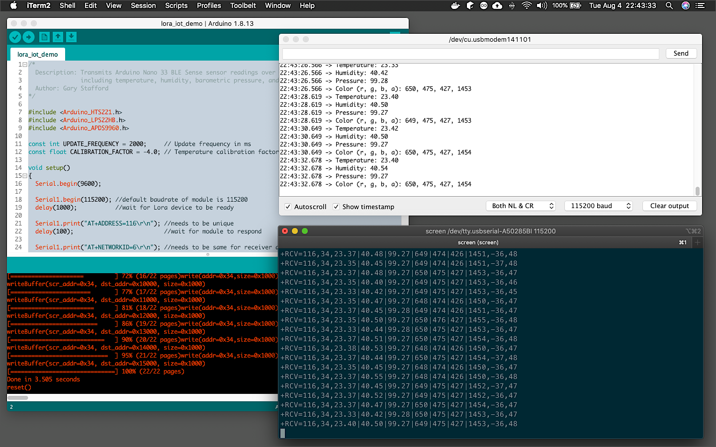
Even easier than the screen command, we can also use the Arduino desktop application's Serial Terminal, as shown in the following short screen recording. Select the correct Port (virtual console) from the Tools menu and open the Serial Terminal. Since the transmitted data should be secured using AES 128-bit data encryption, we need to send an AT command (AT+CPIN) containing the transceiver module’s common password, to correctly decrypt the data on the receiving device (e.g., AT+CPIN=92A0ECEC9000DA0DCF0CAAB0ABA2E0EF).
比screen命令更简单,我们还可以使用Arduino桌面应用程序的Serial Terminal,如下面的简短屏幕录像所示。 从“工具”菜单中选择正确的端口( 虚拟控制台 ),然后打开“串行终端”。 由于应使用AES 128位数据加密来保护传输的数据,因此我们需要发送包含收发器模块公共密码的AT命令( AT+CPIN ),以正确解密接收设备上的数据(例如, AT+CPIN=92A0ECEC9000DA0DCF0CAAB0ABA2E0EF )。
在IoT网关上接收数据 (Receiving Data on IoT Gateway)
The Raspberry Pi will act as an IoT gateway, receiving the environmental sensor data from the IoT device, the Arduino. The Raspberry Pi will run a Python 3 script, rasppi_lora_receiver.py, which will receive and decrypt the data payload, parse the sensor values, and display the values in the terminal. The script uses the pyserial, the Python Serial Port Extension. This Python module encapsulates the access for the serial port.
Raspberry Pi将充当IoT网关,从IoT设备Arduino接收环境传感器数据。 Raspberry Pi将运行Python 3脚本rasppi_lora_receiver.py ,该脚本将接收和解密数据有效负载,解析传感器值并在终端中显示值。 该脚本使用pyserial (Python串行端口扩展名)。 这个Python模块封装了对串行端口的访问。
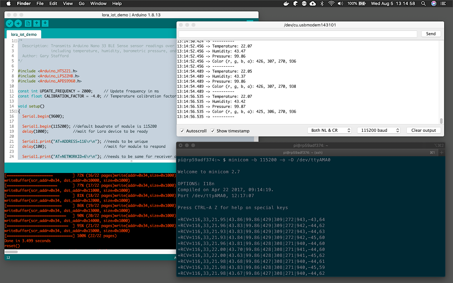
Prior to running the Python script, we can test and debug the connection from the Arduino Sense to the Raspberry Pi using a general application such as Minicom. Minicom is a text-based modem control and terminal emulator program. To install Minicom on the Raspberry Pi, use the following command.
在运行Python脚本之前,我们可以使用Minicom等常规应用程序测试和调试Arduino Sense与Raspberry Pi的连接。 Minicom是基于文本的调制解调器控制和终端仿真器程序。 要在Raspberry Pi上安装Minicom,请使用以下命令。
sudo apt-get install minicomTo run Minicom or the Python script, we will need to know the virtual console of the serial connection (Serial1 in the script) used to communicate with the RYLR896 module, wired to the Raspberry Pi. This can found using the following command.
要运行Minicom或Python脚本,我们将需要了解用于与RYLR896模块通信的串行连接的虚拟控制台(脚本中的Serial1 ),该模块连接到Raspberry Pi。 可以使用以下命令找到。
dmesg | grep -E --color 'serial|tty'Search for a line, similar to the last line, shown below. Note the name of the virtual console, in my case, ttyAMA0.
搜索一行,类似于最后一行,如下所示。 注意虚拟控制台的名称,在我的情况下为ttyAMA0 。
[ 0.000000] Kernel command line: coherent_pool=1M bcm2708_fb.fbwidth=656 bcm2708_fb.fbheight=416 bcm2708_fb.fbswap=1 vc_mem.mem_base=0x1ec00000 vc_mem.mem_size=0x20000000 dwc_otg.lpm_enable=0 console=tty1 root=PARTUUID=509d1565-02 rootfstype=ext4 elevator=deadline fsck.repair=yes rootwait quiet splash plymouth.ignore-serial-consoles[ 0.000637] console [tty1] enabled[ 0.863147] uart-pl011 20201000.serial: cts_event_workaround enabled[ 0.863289] 20201000.serial:ttyAMA0 at MMIO 0x20201000 (irq = 81, base_baud = 0) is a PL011 rev2To view the data received from the Arduino Sense, using Minicom, use the following command, substituting the virtual console value, found above.
要使用Minicom查看从Arduino Sense接收的数据,请使用以下命令替换上面找到的虚拟控制台值。
minicom -b 115200 -o -D /dev/ttyAMA0If successful, we should see output similar to the lower right terminal window. Data is being transmitted by the Arduino Sense and being received by the Raspberry Pi, via LoRaWAN. In the below example, the AES 128-bit data encryption is not enabled on the Arduino, yet. With encryption turned on the sensor data (the payload) would appear garbled.
如果成功,我们应该看到类似于右下方终端窗口的输出。 数据由Arduino Sense传输,并由Raspberry Pi通过LoRaWAN接收。 在以下示例中,尚未在Arduino上启用AES 128位数据加密。 启用加密后,传感器数据( 有效负载 )会出现乱码。
物联网网关Python脚本 (IoT Gateway Python Script)
To run the Python script on the Raspberry Pi, use the following command, substituting the name of the virtual console (e.g., /dev/ttyAMA0).
要在Raspberry Pi上运行Python脚本,请使用以下命令替换虚拟控制台的名称(例如/dev/ttyAMA0 )。
python3 ./rasppi_lora_receiver.py \ --tty /dev/ttyAMA0 --baud-rate 115200The script starts by configuring the RYLR896 module and outputting that configuration to the terminal. If successful, we should see the following informational output.
该脚本首先配置RYLR896模块并将该配置输出到终端。 如果成功,我们应该看到以下信息输出。
Connecting to REYAX RYLR896 transceiver module...Address set? +OKNetwork Id set? +OKAES-128 password set? +OKModule responding? +OKAddress: +ADDRESS=116Firmware version: +VER=RYLR89C_V1.2.7Network Id: +NETWORKID=6UART baud rate: +IPR=115200RF frequency +BAND=915000000RF output power +CRFOP=15Work mode +MODE=0RF parameters +PARAMETER=12,7,1,4AES-128 password of the network +CPIN=92A0ECEC9000DA0DCF0CAAB0ABA2E0EFOnce configured, the script will receive the data from the Arduino Sense, decrypt the data, parse the sensor values, and format and display the values within the terminal.
配置完成后,脚本将从Arduino Sense接收数据,解密数据,解析传感器值,并格式化并在终端中显示这些值。
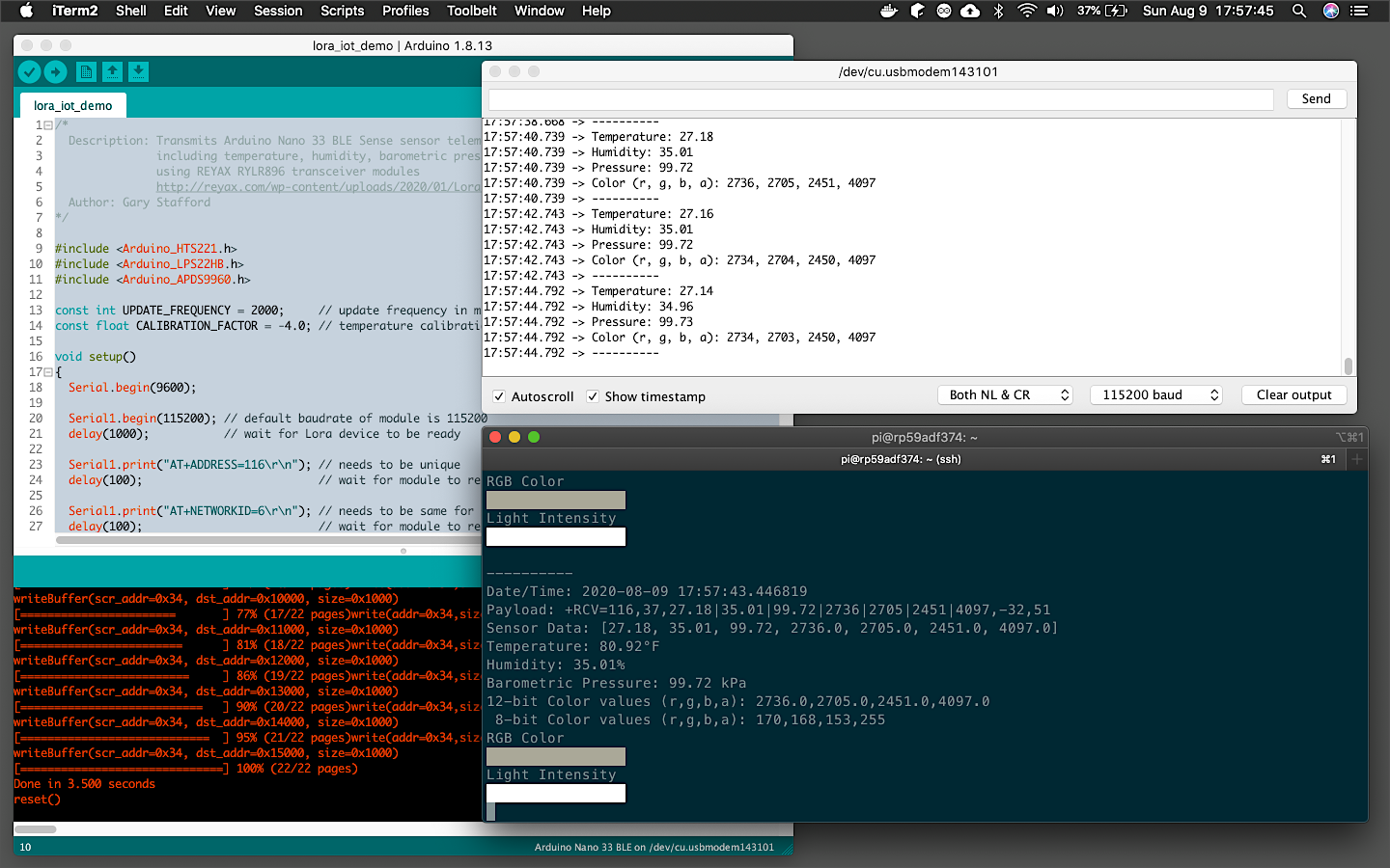
The following screen recording shows a parallel view of both the Arduino Serial Monitor (upper right window) and the Raspberry Pi’s terminal output (lower right window). The Raspberry Pi (receiver) receives data from the Arduino (transmitter). The Raspberry Pi successfully reads, decrypts, interprets, and displays the sensor data, including displaying color swatches for the RGB and light intensity sensor readings.
以下屏幕录像显示了Arduino串行监视器( 右上窗口 )和Raspberry Pi的终端输出( 右下窗口 )的并行视图。 Raspberry Pi( 接收器 )从Arduino( 发送 器 )接收数据。 Raspberry Pi成功读取,解密,解释和显示传感器数据,包括显示RGB的色样和光强度传感器的读数。
结论 (Conclusion)
In this post, we explored the use of the LoRa and LoRaWAN protocols to transmit environmental sensor data from an IoT device to an IoT gateway. Given its low energy consumption, long-distance transmission capabilities, and well-developed protocols, LoRaWAN is an ideal long-range wireless protocol for IoT devices.
在本文中,我们探讨了使用LoRa和LoRaWAN协议将环境传感器数据从IoT设备传输到IoT网关。 鉴于其低能耗,远距离传输能力和完善的协议,LoRaWAN是物联网设备的理想远程无线协议。
This blog represents my own viewpoints and not of my employer, Amazon Web Services.
该博客代表了我自己的观点,而不代表我的雇主Amazon Web Services。
翻译自: https://itnext.io/lora-for-iot-1f91085c5917
lorawan和lora
相关文章:
- 流量卡之家:物联网僵尸网络和DDoS攻击:构建网络风险防火墙
- 工业物联网实施的6个常见误解
- 新型养老机构的“智安”神器 | 钛颐康智慧养老物联网平台
- 4G物联网卡使用记录——使用方法及被锁卡处理
- 中国物联网、物联网卡进入蓬勃发展阶段
- 物联网之智能家居系统设计和实现
- 无缝漫游 无缝漫游
- 【闲置路由器的有效利用】路由器有线桥接实现无线漫游
- 两个华为路由器实现MESH组网,WIFI信号无缝漫游
- 实现酒店无线覆盖和无线漫游
- 无线漫游是 什么?
- 华为无线ensp跨ac三层漫游
- Motorola WLAN之无线漫游
- 2-2 Aruba控制器 无线漫游优化 2020
- 无线漫游原理
- 无线路由器通过有线扩展信号覆盖范围(非桥接方式),实现无缝漫游
- 家用无线漫游组网设置-亲测可用
- 无缝漫游的过程!
- wince之浅谈无线漫游
- 华为AC6605二层组网,配置无线漫游
- WiFi 无缝漫游
- WX系列无线漫游的配置
- 企业级无线无缝漫游之思创漫游3.0 Plus ,三层漫游
- 无线路由器无缝漫游
- 无缝漫游
- 教你设置无线wifi无缝漫游,实现无线wifi自动切换联网
- 多路由器实现无线无缝漫游
- WiFi漫游卡顿严重,如何有效改善实现无缝漫游
- 多个无线 AP 怎么实现无缝漫游?
- ap漫游测试软件,AC+AP方案选择,TP无缝漫游强过UBNT?胖AP如何实现802.11r?
lorawan和lora_用于物联网的LoRa和LoRaWAN相关推荐
- LoRa、LoRaWAN及网关相关技术介绍
LoRa.LoRaWAN及网关技术介绍 1. LoRa与LoRaWAN 2. LoRaWAN协议定义的终端节点工作模式 3. LoRaWan网络架构 4. 组网方式 5. 终端节点→网关:多对一时 6 ...
- 创新微带你了解LoRa与LoRaWAN的区别有哪些
现今物联网飞速发展,相关从业的队伍也愈发壮大,但对于初入行的大家来说,其中的专业名词很容易混淆.接下来就让小编简单介绍下LoRa与LoRaWAN两个专用名词的区别. 很多人以为LoRa代指LoRaWA ...
- lora和lorawan无线技术在物联网的应用
Lora联盟表示:"Lora设备和开放的LoRaWAN协议使智能物联网应用能够解决我们智慧城市建设面临的一些最大挑战:能源管理.自然资源减少.污染控制.基础设施效率.防灾等." L ...
- 深度区分LoRa和LoRaWAN的区别
1.总体介绍 随着物联网技术的飞速发展,NB-IoT.LoRa.SigFox等通信技术名词我们也偶尔有所闻,对于普通人或者是刚刚接触物联网领域的人来说,在一大堆名词前面可能也是分布清楚,本文也将针对L ...
- LoRa及LoRaWAN简介
目录 1.什么是LoRa和LoRaWAN 1.1 LoRa和LoRaWAN的区别 1.2 LoRa扩频技术介绍 1.2.1 什么是扩频技术 1.2.2 扩频技术的作用 1.2.3 扩频技术常用术语介绍 ...
- 学习笔记--浅谈LoRa与LoRaWAN
浅谈LoRa与LoRaWAN 1.什么是LoRa LoRa是semtech公司创建的低功耗局域网无线标准,低功耗一般很难覆盖远距离,远距离一般功耗高,要想马儿不吃草还要跑得远,好像难以办到. LoRa ...
- 认识LoRa以及LoRaWAN
文章目录 1 了解物联网 2 LoRa和NB-IOT 谁主江湖? 3 LoRa和LoRaWAN傻傻分不清楚 3.1 什么是LoRa? 3.1.1 LoRa缺点 3.1.2 LoRa优点 3.2 什么是 ...
- LoRa和LoRaWAN背景及概述
LoRa 简介 LoRa(Long Range)是一种基于超低功耗无线电技术的长距离.低数据速率无线通信技术,能够实现数公里范围内的低功耗.低成本.广域覆盖的物联网通信. LoRa 技术是由 Semt ...
- Lora超全知识归纳,对于lora和lorawan的详细介绍
目录 LORA介绍 LoRa通讯技术 网关信道 网关负载 LoRa模块信道 节点入网 终端LoRa应用方案 设备唤醒 终端LoRa应用实践 网关详情 Lora和loraWAN LoRaWAN 概貌 L ...
- Lora和LoraWAN
Lora和LoraWAN的区别 LoRa经常被误用来描述整个LPWAN通信系统,其实Lora是Semtech拥有的专有调制格式. SX1272和SX1276 LoRa芯片使用称为chirp扩频(CSS ...
最新文章
- Django博客系统注册(图形验证码接口设计和定义)
- linux和android调试概要
- windows kernel 可以直接读写文件系统资料吗_嵌入式杂谈之文件系统
- mysql不同字段full join_Mysql实现full join的替换方法
- FreeRTOS中断配置与临界段
- cookie 保存导航菜单的展开状态
- 为什么要学数据结构?| 原力计划
- python coroutine_Python coroutine的坑
- 3.MongoDB uri中包含特殊字符与读策略配置
- 三极管饱和时内部状态再探
- 汽车故障诊断技术【12】
- serializer嵌套序列化
- eclipse windowJAVA版64位安装教程
- ThinkPHP6项目基操目录
- Python短链接生成、长链接还原,就是这么简单!
- [CTF]利用CRC32绕过RAR密码(适合于小文本文件)
- 抖音logo制作教程
- .obj 和 .mtl文件格式
- 使用设计模式出任CEO迎娶白富美(4)--走马上任,华丽转身
- mysql中real数据类型,SQLite 数据类型 | 菜鸟教程