OpenCV之calib3d 模块. 相机定标和三维重建
使用棋盘格来进行摄像机标定
这节教程的目标是学习怎样通过一系列棋盘照片进行摄像机标定.
测试数据: 使用在你 data 或者 chess 文件夹下的照片.
- 编译带有例子的OpenCV,在cmake的配置中把 BUILD_EXAMPLES 项设置为 ON .
- 打开 bin 文件夹并使用 imagelist_creator 来创建一个包含你的照片列表的 XML/YAML 文件.
- 然后, 运行 calibration 例子来获取摄像机参数. 使用方格的大小等于3厘米.
姿势估计
现在, 让我们写一点代码来检测在一幅图像中的棋盘格,并获取他到摄像机的距离. 你可以使用同样的方法来针对任何已知三维几何结构的物体,这个物体可以在一幅图像中被检测到.
测试数据: 使用来自你的数据文件夹下的 chess_test*.jpg 图片.
创建一个空的控制台项目. 载入一幅图片:
Mat img = imread(argv[1], CV_LOAD_IMAGE_GRAYSCALE);
使用 findChessboard 函数来检测图片中的棋盘.
bool found = findChessboardCorners( img, boardSize, ptvec, CV_CALIB_CB_ADAPTIVE_THRESH );
现在, 定义一个容器 vector<Point3f> 变量,这个数组可以存放在任何坐标系统下的棋盘格三维坐标. 为简便起见, 让我们选择一个棋盘一角在原点并且棋盘在平面 z = 0 上的系统.
从 XML/YAML 文件中读取摄像机参数:
FileStorage fs(filename, FileStorage::READ);
Mat intrinsics, distortion;
fs["camera_matrix"] >> intrinsics;
fs["distortion_coefficients"] >> distortion;
现在我们通过执行函数 solvePnP 可以找到棋盘姿势了:
vector<Point3f> boardPoints;
// 填充数组
...solvePnP(Mat(boardPoints), Mat(foundBoardCorners), cameraMatrix,distCoeffs, rvec, tvec, false);
计算重投影误差,参照例子 calibration (请看 opencv/samples/cpp/calibration.cpp, 函数 computeReprojectionErrors).
问题: 怎样计算摄像机原点到任一角点的距离呢?
Camera calibration With OpenCV
Cameras have been around for a long-long time. However, with the introduction of the cheap pinhole cameras in the late 20th century, they became a common occurrence in our everyday life. Unfortunately, this cheapness comes with its price: significant distortion. Luckily, these are constants and with a calibration and some remapping we can correct this. Furthermore, with calibration you may also determinate the relation between the camera’s natural units (pixels) and the real world units (for example millimeters).
Theory
For the distortion OpenCV takes into account the radial and tangential factors. For the radial one uses the following formula:
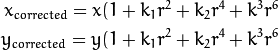
So for an old pixel point at  coordinate in the input image, for a corrected output image its position will be
 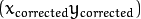 . The presence of the radial distortion manifests in form of the “barrel” or “fish-eye” effect.
Tangential distortion occurs because the image taking lenses are not perfectly parallel to the imaging plane. Correcting this is made via the formulas:
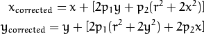
So we have five distortion parameters, which in OpenCV are organized in a 5 column one row matrix:

Now for the unit conversion, we use the following formula:
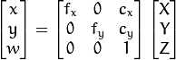
Here the presence of the  is cause we use a homography coordinate system (and
  ). The unknown parameters are
 and
and  (camera focal lengths) and
  what are the optical centers expressed in pixels coordinates. If for both axes a common focal length is used with a given
  aspect ratio (usually 1), then
  and in the upper formula we will have a single
  focal length. The matrix containing these four parameters is referred to as thecamera matrix. While the distortion coefficients are the same regardless of the camera resolutions used, these should be scaled along with the current resolution from the calibrated resolution.
The process of determining these two matrices is the calibration. Calculating these parameters is done by some basic geometrical equations. The equations used depend on the calibrating objects used. Currently OpenCV supports three types of object for calibration:
- Classical black-white chessboard
- Symmetrical circle pattern
- Asymmetrical circle pattern
Basically, you need to take snapshots of these patterns with your camera and let OpenCV find them. Each found pattern equals in a new equation. To solve the equation you need at least a predetermined number of pattern snapshots to form a well-posed equation system. This number is higher for the chessboard pattern and less for the circle ones. For example, in theory the chessboard one requires at least two. However, in practice we have a good amount of noise present in our input images, so for good results you will probably want at least 10 good snapshots of the input pattern in different position.
Goal
The sample application will:
- Determinate the distortion matrix
- Determinate the camera matrix
- Input from Camera, Video and Image file list
- Configuration from XML/YAML file
- Save the results into XML/YAML file
- Calculate re-projection error
Source code
You may also find the source code in the samples/cpp/tutorial_code/calib3d/camera_calibration/ folder of the OpenCV source library or download it from here. The program has a single argument. The name of its configuration file. If none given it will try to open the one named “default.xml”. Here's a sample configuration file in XML format. In the configuration file you may choose to use as input a camera, a video file or an image list. If you opt for the later one, you need to create a configuration file where you enumerate the images to use. Here’s an example ofthis. The important part to remember is that the images needs to be specified using the absolute path or the relative one from your applications working directory. You may find all this in the beforehand mentioned directory.
The application starts up with reading the settings from the configuration file. Although, this is an important part of it, it has nothing to do with the subject of this tutorial: camera calibration. Therefore, I’ve chosen to do not post here the code part for that. The technical background on how to do this you can find in the 输入输出XML和YAML文件 tutorial.
Explanation
Read the settings.
Settings s;
const string inputSettingsFile = argc > 1 ? argv[1] : "default.xml";
FileStorage fs(inputSettingsFile, FileStorage::READ); // Read the settings
if (!fs.isOpened())
{cout << "Could not open the configuration file: \"" << inputSettingsFile << "\"" << endl;return -1;
}
fs["Settings"] >> s;
fs.release();                                         // close Settings fileif (!s.goodInput)
{cout << "Invalid input detected. Application stopping. " << endl;return -1;
}
For this I’ve used simple OpenCV class input operation. After reading the file I’ve an additional post-process function that checks for the validity of the input. Only if all of them are good will be the goodInputvariable true.
Get next input, if it fails or we have enough of them calibrate. After this we have a big loop where we do the following operations: get the next image from the image list, camera or video file. If this fails or we have enough images we run the calibration process. In case of image we step out of the loop and otherwise the remaining frames will be undistorted (if the option is set) via changing from DETECTION mode to CALIBRATED one.
for(int i = 0;;++i)
{Mat view;bool blinkOutput = false;view = s.nextImage();//-----  If no more image, or got enough, then stop calibration and show result -------------if( mode == CAPTURING && imagePoints.size() >= (unsigned)s.nrFrames ){if( runCalibrationAndSave(s, imageSize,  cameraMatrix, distCoeffs, imagePoints))mode = CALIBRATED;elsemode = DETECTION;}if(view.empty())          // If no more images then run calibration, save and stop loop.{if( imagePoints.size() > 0 )runCalibrationAndSave(s, imageSize,  cameraMatrix, distCoeffs, imagePoints);break;imageSize = view.size();  // Format input image.if( s.flipVertical )    flip( view, view, 0 );}
For some cameras we may need to flip the input image. Here we do this too.
Find the pattern in the current input. The formation of the equations I mentioned above consists of finding the major patterns in the input: in case of the chessboard this is their corners of the squares and for the circles, well, the circles itself. The position of these will form the result and is collected into thepointBuf vector.
vector<Point2f> pointBuf;bool found;
switch( s.calibrationPattern ) // Find feature points on the input format
{case Settings::CHESSBOARD:found = findChessboardCorners( view, s.boardSize, pointBuf,CV_CALIB_CB_ADAPTIVE_THRESH | CV_CALIB_CB_FAST_CHECK | CV_CALIB_CB_NORMALIZE_IMAGE);break;
case Settings::CIRCLES_GRID:found = findCirclesGrid( view, s.boardSize, pointBuf );break;
case Settings::ASYMMETRIC_CIRCLES_GRID:found = findCirclesGrid( view, s.boardSize, pointBuf, CALIB_CB_ASYMMETRIC_GRID );break;
}
Depending on the type of the input pattern you use either the findChessboardCorners or the findCirclesGridfunction. For both of them you pass on the current image, the size of the board and you’ll get back the positions of the patterns. Furthermore, they return a boolean variable that states if in the input we could find or not the pattern (we only need to take into account images where this is true!).
Then again in case of cameras we only take camera images after an input delay time passed. This is in order to allow for the user to move the chessboard around and as getting different images. Same images mean same equations, and same equations at the calibration will form an ill-posed problem, so the calibration will fail. For square images the position of the corners are only approximate. We may improve this by calling thecornerSubPix function. This way will get a better calibration result. After this we add a valid inputs result to the imagePoints vector to collect all of the equations into a single container. Finally, for visualization feedback purposes we will draw the found points on the input image with the findChessboardCorners function.
if ( found) // If done with success,{// improve the found corners' coordinate accuracy for chessboardif( s.calibrationPattern == Settings::CHESSBOARD){Mat viewGray;cvtColor(view, viewGray, CV_BGR2GRAY);cornerSubPix( viewGray, pointBuf, Size(11,11),Size(-1,-1), TermCriteria( CV_TERMCRIT_EPS+CV_TERMCRIT_ITER, 30, 0.1 ));}if( mode == CAPTURING && // For camera only take new samples after delay time(!s.inputCapture.isOpened() || clock() - prevTimestamp > s.delay*1e-3*CLOCKS_PER_SEC) ){imagePoints.push_back(pointBuf);prevTimestamp = clock();blinkOutput = s.inputCapture.isOpened();}// Draw the corners.drawChessboardCorners( view, s.boardSize, Mat(pointBuf), found );}Show state and result for the user, plus command line control of the application. The showing part consists of a text output on the live feed, and for video or camera input to show the “capturing” frame we simply bitwise negate the input image.
//----------------------------- Output Text ------------------------------------------------
string msg = (mode == CAPTURING) ? "100/100" :mode == CALIBRATED ? "Calibrated" : "Press 'g' to start";
int baseLine = 0;
Size textSize = getTextSize(msg, 1, 1, 1, &baseLine);
Point textOrigin(view.cols - 2*textSize.width - 10, view.rows - 2*baseLine - 10);if( mode == CAPTURING )
{if(s.showUndistorsed)msg = format( "%d/%d Undist", (int)imagePoints.size(), s.nrFrames );elsemsg = format( "%d/%d", (int)imagePoints.size(), s.nrFrames );
}putText( view, msg, textOrigin, 1, 1, mode == CALIBRATED ?  GREEN : RED);if( blinkOutput )bitwise_not(view, view);
If we only ran the calibration and got the camera matrix plus the distortion coefficients we may just as correct the image with the undistort function:
//------------------------- Video capture  output  undistorted ------------------------------
if( mode == CALIBRATED && s.showUndistorsed )
{Mat temp = view.clone();undistort(temp, view, cameraMatrix, distCoeffs);
}
//------------------------------ Show image and check for input commands -------------------
imshow("Image View", view);
Then we wait for an input key and if this is u we toggle the distortion removal, if it is g we start all over the detection process (or simply start it), and finally for the ESC key quit the application:
char key =  waitKey(s.inputCapture.isOpened() ? 50 : s.delay);
if( key  == ESC_KEY )break;if( key == 'u' && mode == CALIBRATED )s.showUndistorsed = !s.showUndistorsed;if( s.inputCapture.isOpened() && key == 'g' )
{mode = CAPTURING;imagePoints.clear();
}
Show the distortion removal for the images too. When you work with an image list it is not possible to remove the distortion inside the loop. Therefore, you must append this after the loop. Taking advantage of this now I’ll expand the undistort function, which is in fact first a call of the initUndistortRectifyMap to find out the transformation matrices and then doing the transformation with the remap function. Because, after a successful calibration the map calculation needs to be done only once, by using this expanded form you may speed up your application:
if( s.inputType == Settings::IMAGE_LIST && s.showUndistorsed )
{Mat view, rview, map1, map2;initUndistortRectifyMap(cameraMatrix, distCoeffs, Mat(),getOptimalNewCameraMatrix(cameraMatrix, distCoeffs, imageSize, 1, imageSize, 0),imageSize, CV_16SC2, map1, map2);for(int i = 0; i < (int)s.imageList.size(); i++ ){view = imread(s.imageList[i], 1);if(view.empty())continue;remap(view, rview, map1, map2, INTER_LINEAR);imshow("Image View", rview);char c = waitKey();if( c  == ESC_KEY || c == 'q' || c == 'Q' )break;}
}
The calibration and save
Because the calibration needs to be only once per camera it makes sense to save them after a successful calibration. This way later on you can just load these values into your program. Due to this we first make the calibration, and if it succeeds we save the result into an OpenCV style XML or YAML file, depending on the extension you give in the configuration file.
Therefore in the first function we just split up these two processes. Because we want to save many of the calibration variables we’ll create these variables here and pass on both of them to the calibration and saving function. Again, I’ll not show the saving part as that has little in common with the calibration. Explore the source file in order to find out how and what:
bool runCalibrationAndSave(Settings& s, Size imageSize, Mat&  cameraMatrix, Mat& distCoeffs,vector<vector<Point2f> > imagePoints )
{vector<Mat> rvecs, tvecs;vector<float> reprojErrs;double totalAvgErr = 0;bool ok = runCalibration(s,imageSize, cameraMatrix, distCoeffs, imagePoints, rvecs, tvecs,reprojErrs, totalAvgErr);cout << (ok ? "Calibration succeeded" : "Calibration failed")<< ". avg re projection error = "  << totalAvgErr ;if( ok )   // save only if the calibration was done with successsaveCameraParams( s, imageSize, cameraMatrix, distCoeffs, rvecs ,tvecs, reprojErrs,imagePoints, totalAvgErr);return ok;
}
We do the calibration with the help of the calibrateCamera function. This has the following parameters:
The object points. This is a vector of Point3f vector that for each input image describes how should the pattern look. If we have a planar pattern (like a chessboard) then we can simply set all Z coordinates to zero. This is a collection of the points where these important points are present. Because, we use a single pattern for all the input images we can calculate this just once and multiply it for all the other input views. We calculate the corner points with the calcBoardCornerPositions function as:
void calcBoardCornerPositions(Size boardSize, float squareSize, vector<Point3f>& corners,Settings::Pattern patternType /*= Settings::CHESSBOARD*/)
{corners.clear();switch(patternType)
{case Settings::CHESSBOARD:
case Settings::CIRCLES_GRID:for( int i = 0; i < boardSize.height; ++i )for( int j = 0; j < boardSize.width; ++j )corners.push_back(Point3f(float( j*squareSize ), float( i*squareSize ), 0));break;case Settings::ASYMMETRIC_CIRCLES_GRID:for( int i = 0; i < boardSize.height; i++ )for( int j = 0; j < boardSize.width; j++ )corners.push_back(Point3f(float((2*j + i % 2)*squareSize), float(i*squareSize), 0));break;
}
}
And then multiply it as:
vector<vector<Point3f> > objectPoints(1);
calcBoardCornerPositions(s.boardSize, s.squareSize, objectPoints[0], s.calibrationPattern);
objectPoints.resize(imagePoints.size(),objectPoints[0]);
The image points. This is a vector of Point2f vector that for each input image contains where the important points (corners for chessboard, and center of circles for the circle patterns) were found. We already collected this from what the findChessboardCorners or the findCirclesGrid function returned. We just need to pass it on.
The size of the image acquired from the camera, video file or the images.
The camera matrix. If we used the fix aspect ratio option we need to set the
to zero:cameraMatrix = Mat::eye(3, 3, CV_64F); if( s.flag & CV_CALIB_FIX_ASPECT_RATIO )cameraMatrix.at<double>(0,0) = 1.0;
The distortion coefficient matrix. Initialize with zero.
distCoeffs = Mat::zeros(8, 1, CV_64F);
The function will calculate for all the views the rotation and translation vector that transform the object points (given in the model coordinate space) to the image points (given in the world coordinate space). The 7th and 8th parameters are an output vector of matrices containing in the ith position the rotation and translation vector for the ith object point to the ith image point.
The final argument is a flag. You need to specify here options like fix the aspect ratio for the focal length, assume zero tangential distortion or to fix the principal point.
double rms = calibrateCamera(objectPoints, imagePoints, imageSize, cameraMatrix,distCoeffs, rvecs, tvecs, s.flag|CV_CALIB_FIX_K4|CV_CALIB_FIX_K5);
The function returns the average re-projection error. This number gives a good estimation of just how exact is the found parameters. This should be as close to zero as possible. Given the intrinsic, distortion, rotation and translation matrices we may calculate the error for one view by using the projectPoints to first transform the object point to image point. Then we calculate the absolute norm between what we got with our transformation and the corner/circle finding algorithm. To find the average error we calculate the arithmetical mean of the errors calculate for all the calibration images.
double computeReprojectionErrors( const vector<vector<Point3f> >& objectPoints,const vector<vector<Point2f> >& imagePoints,const vector<Mat>& rvecs, const vector<Mat>& tvecs,const Mat& cameraMatrix , const Mat& distCoeffs,vector<float>& perViewErrors)
{vector<Point2f> imagePoints2;
int i, totalPoints = 0;
double totalErr = 0, err;
perViewErrors.resize(objectPoints.size());for( i = 0; i < (int)objectPoints.size(); ++i )
{projectPoints( Mat(objectPoints[i]), rvecs[i], tvecs[i], cameraMatrix,  // projectdistCoeffs, imagePoints2);err = norm(Mat(imagePoints[i]), Mat(imagePoints2), CV_L2);              // differenceint n = (int)objectPoints[i].size();perViewErrors[i] = (float) std::sqrt(err*err/n);                        // save for this viewtotalErr        += err*err;                                             // sum it uptotalPoints     += n;
}return std::sqrt(totalErr/totalPoints);              // calculate the arithmetical mean
}
Results
Let there be this input chessboard pattern that has a size of 9 X 6. I’ve used an AXIS IP camera to create a couple of snapshots of the board and saved it into a VID5 directory. I’ve put this inside theimages/CameraCalibraation folder of my working directory and created the following VID5.XML file that describes which images to use:
<?xml version="1.0"?>
<opencv_storage>
<images>
images/CameraCalibraation/VID5/xx1.jpg
images/CameraCalibraation/VID5/xx2.jpg
images/CameraCalibraation/VID5/xx3.jpg
images/CameraCalibraation/VID5/xx4.jpg
images/CameraCalibraation/VID5/xx5.jpg
images/CameraCalibraation/VID5/xx6.jpg
images/CameraCalibraation/VID5/xx7.jpg
images/CameraCalibraation/VID5/xx8.jpg
</images>
</opencv_storage>
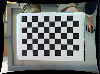
Then specified the images/CameraCalibraation/VID5/VID5.XML as input in the configuration file. Here’s a chessboard pattern found during the runtime of the application:
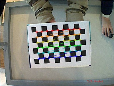
After applying the distortion removal we get:
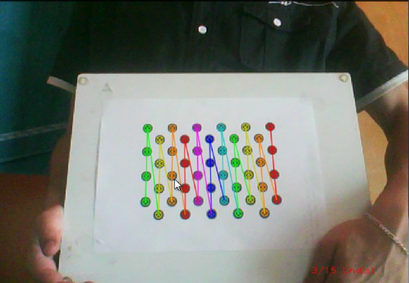
The same works for this asymmetrical circle pattern by setting the input width to 4 and height to 11. This time I’ve used a live camera feed by specifying its ID (“1”) for the input. Here’s, how a detected pattern should look:
In both cases in the specified output XML/YAML file you’ll find the camera and distortion coefficients matrices:
<Camera_Matrix type_id="opencv-matrix">
<rows>3</rows>
<cols>3</cols>
<dt>d</dt>
<data>6.5746697944293521e+002 0. 3.1950000000000000e+002 0.6.5746697944293521e+002 2.3950000000000000e+002 0. 0. 1.</data></Camera_Matrix>
<Distortion_Coefficients type_id="opencv-matrix">
<rows>5</rows>
<cols>1</cols>
<dt>d</dt>
<data>-4.1802327176423804e-001 5.0715244063187526e-001 0. 0.-5.7843597214487474e-001</data></Distortion_Coefficients>
Add these values as constants to your program, call the initUndistortRectifyMap and the remap function to remove distortion and enjoy distortion free inputs with cheap and low quality cameras.
You may observe a runtime instance of this on the YouTube here.
from: http://www.opencv.org.cn/opencvdoc/2.3.2/html/doc/tutorials/calib3d/table_of_content_calib3d/table_of_content_calib3d.html#table-of-content-calib3d
OpenCV之calib3d 模块. 相机定标和三维重建相关推荐
- OpenCV 3最新模块介绍
原文:https://zhuanlan.zhihu.com/p/19988205?columnSlug=hacker-and-painter OpenCV 3 的改动在哪? C 风格的API很快将会消 ...
- OpenCV之feature2d 模块. 2D特征框架(2)特征描述 使用FLANN进行特征点匹配 使用二维特征点(Features2D)和单映射(Homography)寻找已知物体 平面物体检测
特征描述 目标 在本教程中,我们将涉及: 使用 DescriptorExtractor 接口来寻找关键点对应的特征向量. 特别地: 使用 SurfDescriptorExtractor 以及它的函数 ...
- Boost:使用OpenCV在图像或相机框架上应用sobel过滤器
Boost:使用OpenCV在图像或相机框架上应用sobel过滤器 实现功能 C++实现代码 实现功能 Boost的compute模块,使用OpenCV在图像或相机框架上应用sobel过滤器 C++实 ...
- 【相机标定与三维重建原理及实现】学习笔记1——相机模型数学推导详解
目录 前言 一.小孔成像模型 二.坐标系的变换 1.世界坐标系到相机坐标系的变换(刚体变换)[xw^→xc^\boldsymbol {\hat{x_{w}}}\rightarrow \boldsymb ...
- 【python】opencv教程CV2模块——视频捕获,延时摄影视频、鬼畜表情包密集制作
opencv教程CV2模块还可以调用摄像头录制视频呢,没想到吧! 制作延时摄影视频或者鬼畜表情包gif也是轻而易举的事情,等你发挥啦! 代码传送门: import cv2 import timeint ...
- 双目立体视觉源代码 双目立体视觉匹配程序 双目视觉3d成像(三维重构图像处理) 基于双目视觉的深度计算和三维重建 opencv写的双目视觉摄像机标定和三维重建代码
双目视觉/双目标定源码/图片集标定匹配三维重建坐标计算OpenCV 1.双目立体视觉源代码(包括标定,匹配,三维重建) 2.双目视觉实验图片集(双目立体视觉中使用的标准实验图,适合初学者进 行实验使用 ...
- OpenCV编译viz模块
首先需要编译vtk.注意不要使用最新的master版本,而是使用tag分支下的最新版本.当前最新版本是https://gitlab.kitware.com/vtk/vtk/tree/v8.2.0版本. ...
- 超详细!使用OpenCV深度学习模块在图像分类下的应用实践
专注计算机视觉前沿资讯和技术干货 微信公众号:极市平台 官网:https://www.cvmart.net/ 极市导读:本文来自6月份出版的新书<OpenCV深度学习应用与性能优化实践>, ...
- OpenCV:使用OpenCV无缝克隆模块的实例(附完整代码)
使用OpenCV无缝克隆模块的实例 使用OpenCV无缝克隆模块的实例 使用OpenCV无缝克隆模块的实例 #include <signal.h> #include "openc ...
最新文章
- 将 Shiro 作为应用的权限基础
- 基于PYQT编写一个人脸识别软件
- 智能合约重构社会契约 (1)李嘉图合约
- Spring 数据访问那些事儿(二)Spring + JdbcTemplate
- suse 内核编译安装_升级SUSE Linux内核的完整步骤!
- linux 提升cpu权限,CPUlimit有效防止Linux系统CPU过载
- java接口回调测试
- jQuery(二)事件
- 计算机锁定无法安装软件,无法安装软件是什么原因,Win10无法安装应用软件的处理方法...
- 实现div元素在整个屏幕的的垂直居中之translateY(-50%)的利用
- 【九州贯连智能家居——拥抱华为5.5G,打造未来家居公共物联网关,让生活赋能】
- 计算机画图更改,如何用电脑画图功能修改图片与加字
- AWS亚马逊云注册图文详细教程,多币种充值优势分析
- 64位系统最大支持多少内存
- 7-5 手机号码 (20 分)
- 【降价提醒】,您关注的商品已降价!
- 前端linux基础,这一篇就够了
- SuperBrother打鼹鼠
- 幻灯片素材:商务通用PPT动态模板
- Unity的Windows游戏转Android平台的114514个坑